272
PARAMETER
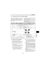
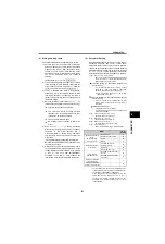
(3) Auto tuning operation
When performing the auto tuning in PU operation
mode, press
or
key in
, and
key in
. When performing auto tuning in
the External operation mode, turn the starting switch
(STF or STR signal) ON.
Since the motor runs when [
Pr. 96 = 101
], caution
must be taken.
Since the RUN signal turns ON when tuning is
started, caution is required especially when a
sequence which releases a mechanical brake by the
RUN signal has been designed.
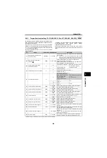
During online auto tuning, only the following I/O
signals are valid (when initial setting):
<Reference> Auto tuning time
To force tuning to end
Enter signal to terminal MRS or RES, or press
during PU operation mode. In External operation
mode, turn OFF the starting switch (STR or STR
signal) to end the operation.
Check the [
Pr. 96
] setting when auto tuning ended.
Normal end................ 3 or 103 is displayed.
Error-activated end........ any of 8, 9, 91, 92, 93 is displayed
When tuning ends normally, press the
key for PU
operation. For External operation, turn OFF the starting
switch (STF or STR signal) once. This operation resets the
auto tuning, and the PU's monitor display returns to the
normal indication.
Without this operation, next operation cannot be done.
When tuning was ended due to an error, the auto tuning did
not end correctly and motor constants have not been set.
Perform an inverter reset (refer to page 57) and restart
tuning.
When using a motor which meets the below description,
set [
Pr. 9 Electronic thermal O/L relay
] again as below after
tuning has completed.
(a) When using motors with rated power specifica-
tions of 200/220V (400/440V) 60Hz, set the value
multiplied by 1.1 for the rated motor current value
in [
Pr. 9
].
(b) When using a motor with a temperature detector
such as PTC thermistor and Klixon to protect the
motor from heat, set [
Pr. 9
=0] (motor overheat
protection by the inverter disabled).
Do not change the [
Pr. 96
] setting after completion of tuning
(3, 13 or 103). When the [
Pr. 96
] setting is changed, tuning
data is invalid. Therefore, perform tuning again. Monitor is
displayed on the operation panel (FR-DU07) and
parameter unit (FR-PU04, FR-PU07) during tuning as
shown in the next page.
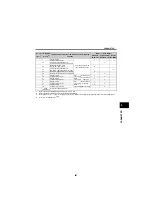
Input terminals
<valid signal>
STOP
,
OH
,
MRS
,
RT
,
RES
,
STF
,
STR
MRS
,
RES
,
STF
,
STR
STF
,
STR
Output
terminal
RUN
,
OL
,
IPF
,
FM*
,
AM*
,
A1B1C1
RUN
,
FM*
,
ABC
* When output frequency and rotation speed are output
from terminal FM and AM, offline auto tuning status (full
scale when ended normally) is output (in 15 levels in
, 8 levels in
, 5 levels in
.)
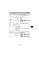
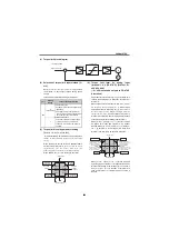
[
Pr. 96
]
Time
1: Non-rotation mode
Estimated time when the SF-JR is
4-pole
0.4kW : 22s
3.7kW : 37s
11kW : 50s
37kW : 90s
75kW : 130s
11: Non-rotation mode
(Tunes only R1)
About 9s
101: Rotation mode
About 40s*
* Auto tuning time varies with the acceleration and
deceleration time settings as indicated below.
Auto tuning time
= acceleration time + deceleration time + about 30s
A700
E700
D700
A700
E700
D700
A700
E700 D700
A700
E700
D700
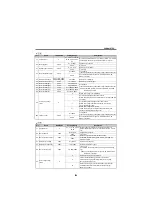
Error
Display
Error Cause
Remedy
8
Forced End
Set [
Pr. 96 = 1
,
11 or
101
] and perform tuning
again
9
Inverter protective
function operation
Make setting again.
91
Current limit
(stall prevention)
function was activated.
Increase acceleration/
deceleration time.
Set [
Pr. 156 = 1
].
92
Converter output voltage
reached 75% of rated
value.
Check for fluctuation of
power supply voltage.
93
Calculation error
A motor is not connected.
Check the motor wiring
and make setting again.
Содержание FR-A700 Series
Страница 245: ...279 2 PARAMETER PARAMETER MEMO ...
Страница 440: ...474 PARAMETER MEMO ...
Страница 522: ...556 SELECTION MEMO ...


