


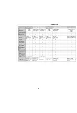


12
SPECIFICATIONS
(3) FR-E700
C
ont
rol
s
peci
fic
ati
on
s
Control method
Soft-PWM control/high carrier frequency PWM control (V/F control, Advanced magnetic flux vector control,
General-purpose magnetic flux vector control, Optimum excitation control can be selected)
Output frequency range
0.2 to 400Hz
Frequency setting
resolution
Analog input
0.06Hz/60Hz (terminal2, 4: 0 to 10V/10bit)
0.12Hz/60Hz (terminal2, 4: 0 to 5V/9bit)
0.06Hz/60Hz (terminal4: 0 to 20mA/10bit)
Digital input
0.01Hz
Frequency accuracy
Analog input
Within
±
0.5% of the max. output frequency (25°C
±
10°C)
Digital input
Within 0.01% of the set output frequency
Voltage/frequency characteristics
Base frequency can be set from 0 to 400Hz, constant-torque/variable torque pattern can be selected
Starting torque
200% or more (at 0.5Hz)...when Advanced magnetic flux vector control is set (3.7K or less)
Torque boost
Manual torque boost
Acceleration/deceleration time setting
0.01 to 360s, 0.1 to 3600s (acceleration and deceleration can be set individually), linear or S-pattern acceleration/
deceleration mode can be selected.
Braking torque
Regenerative
0.1K, 0.2K ..... 150%,
0.4K, 0.75K ..... 100%,
1.5K ..... 50%,
2.2K or more ..... 20%
DC injection brake Operation frequency (0 to 120Hz), operation time (0 to 10s), operation voltage (0 to 30%) variable
Stall prevention operation level
Operation current level can be set (0 to 200% adjustable), whether to use the function or not can be selected
Ope
rat
ion s
peci
fic
ati
o
ns
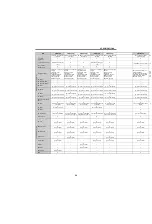
Frequency setting
signal
Analog input
Two points
Terminal 2: 0 to 10V, 0 to 5V can be selected
Terminal 4: 0 to 10V, 0 to 5V, 4 to 20mA can be selected
Digital input
Entered from operation panel and parameter unit
Start signal
Forward and reverse rotation or start signal automatic self-holding input (3-wire input) can be selected.
Input signal
Seven points
You can select from among multi-speed selection, remote setting, stop-on contact selection, second function
selection, terminal 4 input selection, JOG operation selection, PID control valid terminal, brake opening
completion signal, external thermal input, PU-External operation switchover, V/F switchover, output stop, start
self-holding selection, forward rotation, reverse rotation command, inverter reset, PU-NET operation switchover,
External-NET operation switchover, command source switchover, inverter operation enable signal, and PU
operation external interlock
Operational functions
Maximum/minimum frequency setting, frequency jump operation, external thermal relay input selection,
automatic restart after instantaneous power failure operation, forward/reverse rotation prevention, remote setting,
brake sequence, second function, multi-speed operation, stop-on contact control, droop control, regeneration
avoidance, slip compensation, operation mode selection, offline auto tuning function, PID control, computer link
operation (RS-485)
Ou
tp
ut
si
gn
al
Output signal
points
Open collector
output
Two points
Relay output
One point
Operating status
You can select from among inverter operation, up-to-frequency, overload alarm, output frequency detection,
regenerative brake prealarm, electronic thermal relay function prealarm, inverter operation ready, output current
detection, zero current detection, PID lower limit, PID upper limit, PID forward/reverse rotation output, brake
opening request, fan alarm
, heatsink overheat pre-alarm, deceleration at an instantaneous power failure, PID
control activated, during retry, life alarm, current average value monitor, remote output, alarm output, fault output,
fault output 3, and maintenance timer alarm
Output point for
meter
Pulse output
MAX 2.4kHz: one point
For meter
You can select from among output frequency, motor current (steady), output voltage, frequency setting, motor
torque, converter output voltage, regenerative brake duty, electronic thermal relay function load factor, output
current peak value, converter output voltage peak value, reference voltage output, motor load factor, PID set
point, PID measured value, output power
Pulse train output (1440 pulse/s/full scale)
In
dica
tion
Operation panel
Parameter unit (FR-
PU07)
Operating status
You can select from among output frequency, motor current (steady), output voltage, frequency setting,
cumulative energization time, actual operation time, motor torque, converter output voltage, regenerative brake
duty, electronic thermal relay function load factor, output current peak value, converter output voltage peak value,
motor load factor, PID set point, PID measured value, PID deviation, inverter I/O terminal monitor, I/O terminal
option monitor, output power, cumulative power, motor thermal load factor, and inverter thermal load factor.
Fault definition
Fault definition is displayed when the fault occurs and the past 8 fault definitions (output voltage/current/
frequency/cumulative energization time right before the fault occurs) are stored
Additional display by
the parameter unit
(FR-PU04/FR-PU07)
only
Operating status
Not used
Fault definition
Output voltage/current/frequency/cumulative energization time immediately before the fault occurs
Interactive
guidance
Function (help) for operation guide
Содержание FR-A700 Series
Страница 245: ...279 2 PARAMETER PARAMETER MEMO ...
Страница 440: ...474 PARAMETER MEMO ...
Страница 522: ...556 SELECTION MEMO ...