101
1
S
PECIFI
C
A
T
IONS
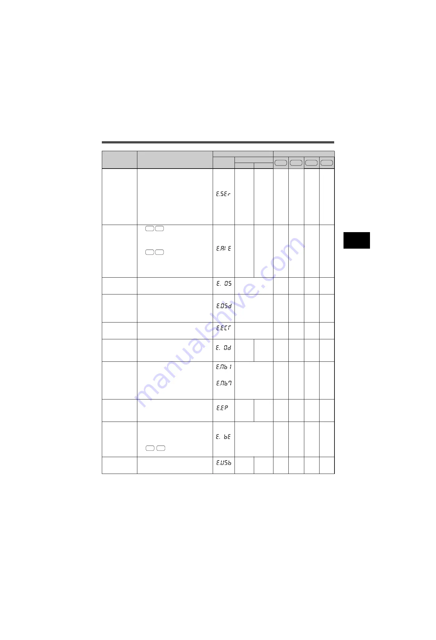
SPECIFICATIONS
Communication
fault (inverter)
This function stops the inverter output when
communication error occurs consecutively
for more than permissible retry count when
a value other than "9999" is set in [
Pr. 335
RS-485 communication retry
] during RS-485
communication from the RS-485 terminals.
This function also stops the inverter output if
communication is broken for the period of
time set in [
Pr. 336 RS-485 communication
check time interval
].
(E.SER)
Fault 14
VFD
Comm
error
{
{
—
—
Analog input fault
For
, the fault appears when
30mA or more is input or a voltage (7.5V or
more) is input with the terminal 2 or 4 set to
current input.
For
, the fault appears if
voltage(current) is input to terminal 4 when the
setting in [
Pr.267 Terminal 4 input selection
] and
the setting of voltage/current input switch are
different.
(E.AIE)
Fault 14
Analog in
error
{
{
{
{
Overspeed
occurrence
Indicates that the motor speed exceeds the
over speed setting level during encoder
feedback control and vector control.
(E.OS)
E.OS
{
—
—
—
Speed deviation
excess detection
Stops the inverter output if the motor speed
is increased or decreased under the
influence of the load etc. during vector
control and cannot be controlled in
accordance with the speed command value.
(E.OSD)
E.OSd
{
—
—
—
Signal loss
detection
Trips the inverter output when the encoder
signal is shut off under orientation control,
encoder feedback control or vector control.
(E.ECT)
E.ECT
{
—
—
—
Excessive position
error
Indicates that the difference between the
position command and position feedback
exceeded the reference under position
control.
(E.OD)
Fault 14
E.Od
{
—
—
—
Brake sequence
error
The inverter output is stopped when a
sequence error occurs during use of the
brake sequence function [
Pr. 278 to Pr. 285
Brake sequence function
]
.
(E.MB1to
E.MB7)
E.MB1 Fault to
E.MB7 Fault
{
—
{
—
Encoder phase
error
Appears when rotation command of the
inverter differs from the actual motor rotation
direction detected from the encoder during
offline auto tuning.
(E.EP)
Fault 14
Encoder
phase
error
{
—
—
—
Brake transistor
alarm detection
This function stops the inverter output if an
alarm occurs in the brake circuit, e.g.
damaged brake transistors. In this case, the
inverter must be powered OFF immediately.
For
, it also appears when an
internal circuit fault occurs.
(E.BE)
Br. Cct. Fault
{
{
{
{
USB
communication
fault
When communication has broken during the
time set in [
Pr. 548 USB communication check
time interval
], this function trips the inverter.
(E.USB)
Fault 14
USB
comm
error
{
—
{
—
Name
Description
Indication
Available Inverters
Operation
panel
Parameter unit
FR-PU04 FR-PU07
A700
F700
E700
D700
A700 F700
E700 D700
to
A700
F700
Содержание FR-A700 Series
Страница 245: ...279 2 PARAMETER PARAMETER MEMO ...
Страница 440: ...474 PARAMETER MEMO ...
Страница 522: ...556 SELECTION MEMO ...


