


31
1
S
PECIFI
C
A
T
IONS
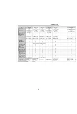
SPECIFICATIONS
Cont
act
input
PC
Contact
input
common
terminal
(source)
Power supply voltage range :
19.2 to 28.8VDC
22 to 26.5VDC
Permissible load current :
100mA
When connecting the transistor
output (open collector output), such
as a programmable controller, when
sink logic is selected, connect the
external power supply common for
transistor output to this terminal to
prevent a malfunction caused by
undesirable currents.
{
{
{
{
External
transistor
common
terminal
(initial
setting)
Common terminal for contact input
terminal (source logic).
24VDC
power
supply
Can be used as 24VDC 0.1A power
supply.
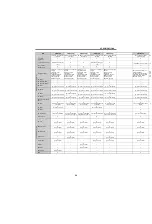
F
requency
set
ting
10E
Frequency
setting
power
supply
terminal
10V 0.4VDC
Permissible load current :
10mA
Used as power supply when
connecting potentiometer for
frequency setting (speed setting)
from outside of the inverter.
When connecting a frequency setting
potentiometer to
at
an initial status, connect it to terminal
10.
Change the input specifications of
terminal 2 with [
Pr. 73
] when
connecting it to terminal 10E.
{
{
—
—
10
5.2V 0.2VDC
5.0V 0.2VDC
Permissible load current :
10mA
{
{
{
{
2
Frequency
setting
signal
terminal
(voltage
signal)
[Voltage input]
Input resistance : 10k
1k
Maximum permissible voltage :
20VDC
[Current input]
Input resistance : 245
5
Maximum permissible current :
30mA
[Voltage input]
Input resistance : 10k
1k
Maximum permissible voltage :
20VDC
Inputting 0 to 5VDC (or 0 to 10V, 0 to
20mA) provides the maximum output
frequency at 5V (10V, 20mA) and
makes input and output proportional.
Use [
Pr. 73
] to switch from among
input 0 to 5VDC (initial setting), 0 to
10VDC, and 0 to 20mA.
For
, set the voltage/
current input switch in the ON
position to select current input (0 to
20mA).
{
{
{
{
PTC input
terminal
Specification of applicable PTC
thermistor
Overheat detection resistance:
500 to 30k
(set to [
Pr. 561
])
Connect a PTC thermistor between
terminal 10 and 2.
Setting PTC thermistor active ([
Pr.
561
≠
9999]) disables the frequency
setting in terminal 2.
—
—
—
{
4
Frequency
setting
signal
terminal
(current
signal)
[Current input]
Input resistance :
245
5
233
5
Maximum permissible current :
30mA
[Voltage input]
Input resistance : 10k
1k
Maximum permissible voltage :
20VDC
Inputting 4 to 20mADC (or 0 to 5V, 0
to 10V) provides the maximum output
frequency at 20mA and makes input
and output proportional. This input
signal is valid only when the AU
signal is ON (terminal 2 input is
invalid). Use [
Pr. 267
] to switch from
among input 4 to 20mA (initial
setting), 0 to 5VDC and 0 to 10VDC.
For
, set the voltage/
current input switch in the OFF
position to select voltage input (0 to
5V/0 to 10V). Use [
Pr. 858
] to switch
terminal functions.
To input voltage (0 to 5V / 0 to 10V) in
, set the voltage/
current input switch to "V".,
{
{
{
{
1
Frequency
setting
auxiliary
input
terminal
Input resistance : 10k
1k
Maximum permissible voltage :
20VDC
Inputting 0 to 5 VDC or 0 to
10VDC adds this signal to terminal
2 or 4 frequency setting signal.
Use [
Pr. 73
] to switch between input 0
to 5VDC and 0 to 10VDC (initial
setting) input.
{
{
—
—
5
Frequency
setting
signal
terminal
common
terminal
—
Common terminal for frequency
setting signal (terminal 2, 1 or 4) and
analog output terminal AM.
Isolated from terminals SD and SE.
Do not earth (ground).
{
{
{
{
Ty
p
e Terminal
Symbol
Terminal
Name
Rating, etc.
Application Explanation
Available Inverters
Refer
to
Page
A700
F700
E700
D700
A700
F700
E700
D700
A700
F700
A700
F700
E700
D700
A700
F700
E700
D700
A700
F700
A700
F700
E700
D700
A700
F700
E700
D700
Содержание FR-A700 Series
Страница 245: ...279 2 PARAMETER PARAMETER MEMO ...
Страница 440: ...474 PARAMETER MEMO ...
Страница 522: ...556 SELECTION MEMO ...