223
2
P
ARAM
ETE
R
PARAMETER
(6) Override function [
Pr. 252, 253
]
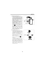
Use the override function to change the main speed
at a fixed ratio.
When an override is selected, the terminal 1 or
terminal 4 is used for the main speed setting and the
terminal 2 for the override signal. (When the main
speed of the terminal 1 or terminal 4 is not input,
compensation by the terminal 2 is invalid.)
When inputting compensation to multi-speed
operation or remote setting, set [
Pr. 28 Multi-speed
input compensation selection
= 1] .(Refer to page 227)
Using [
Pr. 252, 253
], set the override range. Use a
following formula for the set frequency for override.
Main speed set frequency (Hz): Terminal 1, 4 input, multi-
speed setting
Compensation amount (%): Terminal 2 input
Example: When [
Pr. 73 = 5
]
Set
frequency
(Hz)
= Main speed set frequency (Hz)
A700
F700
Compensation
amount(%)
100(%)
Bias
[
Pr.252
]
0V
2.5V
(5V)
5V
(10V)
0
50
100
150
200
Initial value
(50% to 150%)
Voltage across terminals 2 and 5
Override value (%)
Gain
[
Pr.253
]
The set frequency changes as shown below according
to the terminal 1 (main speed) and terminal 2
(auxiliary) inputs.
Override connection diagram
10
2
5
Forward
rotation
Main
speed
Inverter
STF
1
(-)
(+)
Override
setting
SD
0
2.5
5
0
Terminal 1 input voltage (V)
Set frequency (Hz)
Terminal 2
5VDC input(150%)
Terminal 2
0V input(50%)
Terminal 2
2.5VDC input(100%)
30
15
60
45
90
[
Pr.
]
Name
Initial Value
Setting
Range
Description
252
Override bias
50%
0 to 200%
Set the bias side compensation value of override function.
253
Override gain
150%
0 to 200%
Set the gain side compensation value of override function.
Содержание FR-A700 Series
Страница 245: ...279 2 PARAMETER PARAMETER MEMO ...
Страница 440: ...474 PARAMETER MEMO ...
Страница 522: ...556 SELECTION MEMO ...


