374
PARAMETER
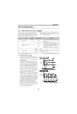
(1) Connection and parameter setting
For
, remove a jumper across terminals R/
L1-R1/L11 and terminals S/L2-S1/L21 and connect
terminal R1/L11 to terminal P/+ and terminal S1/L21 to
terminal N/-.
When [
Pr. 261
0] and an undervoltage or power failure
occurs, undervoltage protection (E.UVT) or
instantaneous power failure protection (E.IPF) is not
provided, but power failure deceleration is made.
If input phase is lost when[
Pr. 872
= 1] (input phase loss
protection provided) and [
Pr. 261
≠
0], input phase failure
protection (E.ILF) is not provided but power-failure
deceleration is made.
When [
Pr. 261
≠
0] in
, inverter decelerates to a
stop at undervoltage and power failure.
(2) Operation outline of deceleration to stop
at power failure
If an undervoltage or power failure occurs in
, the output frequency is dropped by the
frequency set in [
Pr. 262 Subtracted frequency at
deceleration start
], and deceleration is made for the
deceleration time set in [
Pr. 264 Power-failure
deceleration time 1
]. (Deceleration time setting is the
time taken from the [
Pr. 20 Acceleration/deceleration
reference frequency
] to a stop.)
When the frequency is low and enough regeneration
energy is not provided, for example, the deceleration
time (slope) from [
Pr. 266 Power failure deceleration
time switchover frequency
] to a stop can be changed
using [
Pr. 265 Power-failure deceleration time 2
] .
When [
Pr. 30 Regenerative function selection
= 2] (FR-HC,
MT-HC, FR-CV is used), the power failure deceleration
function is invalid.
When the (output frequency - [
Pr. 262
]) at
undervoltage or power failure occurrence is negative,
the calculation result is regarded as 0Hz (DC
injection brake operation is performed without
deceleration).
If an undervoltage or power failure occurs in
, the output frequency is decreased and
controlled to decrease to 0Hz by keeping the voltage
in the converter section (bus voltage) steady.
Power failure stop function does not operate during a
stop or trip.
(3) Power failure stop mode [Pr. 261 = 1, 11
*
]
(*not available for
)
If power is restored during power failure deceleration,
deceleration to a stop is continued and the inverter remains
stopped. To restart, turn OFF the start signal once, then turn it
ON again.
After a power failure stop, the inverter will not start even
if the power is turned ON with the start signal (STF/STR)
input. After switching ON the power, turn OFF the start
signal once and then ON again to make a start.
When automatic restart after instantaneous power
failure is selected ([
Pr. 57
≠
9999]) , power failure stop
function is made invalid and automatic restart operation
after instantaneous power failure is performed.
A700 F700
Power supply
Remove the jumper
Inverter
S/L2
T/L3
S1/L21
P/+
N/
−
R1/L11
R/L1
Connect terminals
R1/L11 and P/+
and terminals
S1/L21 and N/-.
E700 D700
A700 F700
[
Pr. 264
]
Power-failure
deceleration time 1
[
Pr. 265
]
Power-failure
deceleration
time 2
Time
Power supply
Output
frequency
Subtracted
frequency at
deceleration start
[
Pr. 262
]
Power-failure
deceleration
time switchover
frequency
[
Pr. 266
]
E700 D700
F700
E700
D700
During deceleration at
occurrence of power failure
During stop at
occurrence of
power failure
STF
Y46
Time
Turn OFF STF once to make acceleration again
Power
supply
Output frequency
[
Pr.261
= 1]
A700 F700
E700 D700
During deceleration at
occurrence of power failure
During stop at
occurrence of
power failure
STF
Y46
Time
Turn OFF STF once to make acceleration again
Power
supply
Output frequency
[
Pr.261
= 1]
Содержание FR-A700 Series
Страница 245: ...279 2 PARAMETER PARAMETER MEMO ...
Страница 440: ...474 PARAMETER MEMO ...
Страница 522: ...556 SELECTION MEMO ...


