222
PARAMETER
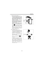
(5) Additional compensation
(
Pr. 242, 243
)
The compensation signal can be added to the main
speed setting for synchronous/continuous speed
control operation, etc.
The compensation input of the terminal 1 can also be
added to the multi-speed setting or terminal 4 (initial
value 4 to 20mA).
The added compensation for terminal 2 can be
adjusted by [
Pr. 242
], and the compensation for
terminal 4 by [
Pr. 243
].
Auxiliary input characteristics
Analog
command value
using terminal 2
= Terminal 2 input + Terminal 1 input
Analog
command value
using terminal 4
= Terminal 4 input + Terminal 1 input
A700
F700
[
Pr. 242
]
100(%)
[
Pr. 243
]
100(%)
Added compensation
connection example
10
2
5
Forward
rotation
Inverter
STF
1
Auxiliary input
0 to 10V ( 5V)
SD
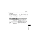
Output frequency
When voltage across
terminals 2 and 5 is 2.5V
(5V)
When voltage
across terminals 2
and 5 is 0V
+5V
(+10V)
Terminal 1
0
-2.5V
(-5V)
-5V
(-10V)
STF Signal
ON
STF Signal
ON
Forward rotation
Forward rotation
When [
Pr. 73
] setting is 0 to 5
+2.5V
(+5V)
Output frequency
When voltage across
terminals 2 and 5 is 2.5V
(5V)
When voltage
across terminals 2
and 5 is 0V
+5V
(+10V)
Terminal 1
0
-2.5V
(-5V)
-5V
(-10V)
Forward rotation
Forward rotation
When [
Pr. 73
] setting is 10 to 15
Reverse rotation
Reverse rotation
+2.5V
(+5V)
STF Signal
ON
STF Signal
ON
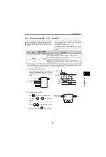
[
Pr.
]
Name
Initial Value
Setting Range
Description
242
Terminal 1 added compensation
amount (terminal 2)
100%
0 to 100%
Set the ratio of added compensation
amount when terminal 2 is the main
speed.
243
Terminal 1 added compensation
amount (terminal 4)
75%
0 to 100%
Set the ratio of added compensation
amount when terminal 4 is the main
speed.
Содержание FR-A700 Series
Страница 245: ...279 2 PARAMETER PARAMETER MEMO ...
Страница 440: ...474 PARAMETER MEMO ...
Страница 522: ...556 SELECTION MEMO ...


