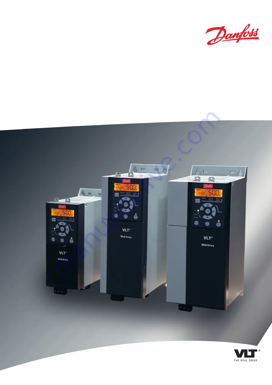
manualshive.com logo in svg
background image

MAKING MODERN LIVING POSSIBLE

Instruction Manual

VLT

®

 Midi Drive FC 280

www.DanfossDrives.com

Содержание VLT Midi Drive FC 280

Страница 1: ...MAKING MODERN LIVING POSSIBLE Instruction Manual VLT Midi Drive FC 280 www DanfossDrives com...

Страница 2: ......

Страница 3: ...allation 10 4 1 Safety Instructions 10 4 2 EMC compliant Installation 10 4 3 Grounding 10 4 4 Wiring Schematic 12 4 5 Access 14 4 6 Motor Connection 14 4 7 AC Line Input Connection 15 4 8 Control Wiri...

Страница 4: ...of Warnings and Alarms 44 8 5 Troubleshooting 46 9 Specifications 48 9 1 Electrical Data 48 9 2 Line Power Supply 3 phase 50 9 3 Motor Output and Motor Data 50 9 4 Ambient Conditions 50 9 5 Cable Spec...

Страница 5: ...Use The adjustable frequency drive is an electronic motor controller intended for Regulation of motor speed in response to system feedback or to remote commands from external controllers A power drive...

Страница 6: ...re sizes and power ratings of the adjustable frequency drives refer to chapter 9 9 Enclosure Sizes Power Ratings and Dimensions 1 4 4 Safe Torque Off STO The VLT Midi Drive FC 280 adjustable frequency...

Страница 7: ...AC mains DC supply or load sharing the motor may start at any time Unintended start during programming service or repair work can result in death serious injury or property damage The motor can start...

Страница 8: ...ating shafts and electrical equipment can result in death or serious injury Ensure that only trained and qualified personnel perform installation start up and maintenance Ensure that electrical work c...

Страница 9: ...igure 3 1 Product Nameplate Example NOTICE Do not remove the nameplate from the adjustable frequency drive loss of warranty 3 1 2 Storage Ensure that requirements for storage are fulfilled Refer to ch...

Страница 10: ...entilation on the side 130BE615 10 Figure 3 3 Side by side Installation CAUTION RISK OF OVERHEATING If IP21 solution is used mounting the units side by side could lead to overheating and unit damages...

Страница 11: ...Plate with Screws 130BE481 10 1 2 1 Vertical decoupling plate 2 Screws Figure 3 5 Fasten the Vertical Decoupling Plate with Screws Both Figure 3 4 and Figure 3 5 show PROFINET sockets The actual socke...

Страница 12: ...it and overcurrent protection If fuses are not factory supplied the installer must provide them See maximum fuse ratings in chapter 9 8 Fuses and Circuit Breakers Wire type and ratings All wiring must...

Страница 13: ...equipment see chapter 4 6 Motor Connection Use high strand wire to reduce electrical interference Do not use pigtails NOTICE POTENTIAL EQUALIZATION Risk of electrical interference when the ground pote...

Страница 14: ...02 01 24 V NPN 0 V PNP 0 V PNP 24 V NPN 19 D IN 24 V NPN 0 V PNP 27 D IN OUT 24 V 0 V 0 V PNP 24 V NPN 29 D IN 24 V NPN 0 V PNP 0 V PNP 24 V NPN 33 D IN 32 D IN 38 D IN 37 D IN 95 P 5 00 2 1 ON DC R...

Страница 15: ...r 2 Adjustable frequency drive 7 Motor 3 phase and PE 3 Output contactor generally not recommended 8 Line power single phase 3 phase and reinforced PE 4 Grounding rail PE 9 Control wiring 5 Cable shie...

Страница 16: ...r motor or slip ring induction motor between the adjustable frequency drive and the motor Procedure 1 Strip a section of the outer cable insulation 2 Position the stripped cable under the cable clamp...

Страница 17: ...ect the input power to the line power input terminals or the input disconnect 3 Ground the cable in accordance with the grounding instructions in chapter 4 3 Grounding 4 When supplied from an isolated...

Страница 18: ...al 33 Digital Input 16 Preset ref bit 0 37 38 STO Functional safety inputs Analog inputs outputs Terminal Parameter Default setting Description 42 Parameter 6 91 Ter minal 42 Analog Output 0 No operat...

Страница 19: ...etween control terminal 12 recommended or 13 to terminal 27 The jumper provides an internal 24 V signal on terminal 27 Only for GLCP When the status line at the bottom of the LCP reads AUTO REMOTE COA...

Страница 20: ...rial communication set up select the following 1 Protocol type in parameter 8 30 Protocol 2 Adjustable frequency drive address in parameter 8 31 Address 3 Baud rate in parameter 8 32 Baud Rate Two com...

Страница 21: ...and bottom clearance is adequate to ensure proper air flow for cooling see chapter 3 3 Mounting Ambient conditions Check that requirements for ambient conditions are met Fusing and circuit breakers C...

Страница 22: ...motor 5 2 Applying Power Apply power to the adjustable frequency drive using the following steps 1 Confirm that the input voltage is balanced within 3 If not correct the input voltage imbalance before...

Страница 23: ...meters and within parameters or increasing decreasing parameter values Arrows can also be used for setting local reference 1 1 OK Press to access parameter groups or to enable a selection 1 2 For movi...

Страница 24: ...first parameter in the next parameter group for example move from parameter 0 03 Regional Settings 0 International to parameter 1 00 Configuration Mode 0 Open loop NOTICE During start up the LCP show...

Страница 25: ...24 XXXX A 1 20 XXXX kW 1 22 XXXX V Motor nominal speed PM Motor Asynchronous Motor Motor power Motor voltage Motor Cont Rated Torque 1 26 XXXX 1 23 XXXX Hz Stator Resistance Motor frequency 1 25 XXXX...

Страница 26: ...her Back twice or three times for array parameters to enter Main Menu or press Menu once to enter Status See Figure 5 5 Figure 5 6 and Figure 5 7 for the principles of changing the value of continuous...

Страница 27: ...s shown 2 Press OK to start editing 3 Change parameter value flashing 4 Press Back to cancel changes or OK to accept changes return to screen 2 5 Select a parameter within the group 6 Back Removes the...

Страница 28: ...9 Alarm Log Displays a list of current warnings the last 10 alarms and the maintenance log Table 5 9 Legend to Figure 5 8 Display Menu Keys C Navigation keys and LEDs Navigation keys are used for pro...

Страница 29: ...eter group 3 Press to browse through the parameters press OK to select a parameter 4 Press to change the value of a parameter setting 5 Press to shift digit when a decimal parameter is in the editing...

Страница 30: ...Parameter 1 24 Motor Current 5 Parameter 1 25 Motor Nominal Speed For optimum performance in VVC mode extra motor data is required to set up the following parameters The data is found in the motor da...

Страница 31: ...g of these parameters for applications with high inertia Start the motor at nominal speed If the application does not run well check the VVC PM settings Table 5 13 shows recommendations in different a...

Страница 32: ...b Verify that the LCP direction arrow is clockwise When parameter 1 06 Clockwise Direction is set to 1 Inverse counter clockwise a Verify that the motor turns counter clockwise b Verify that the LCP...

Страница 33: ...the speed range 4 Remove the external run command 5 Check the sound and vibration levels of the motor to ensure that the system is working as intended If warnings or alarms occur see chapter 8 2 Warni...

Страница 34: ...1 STO Architecture Terminal 37 Terminal 38 Torque Warning or alarm Energized1 Energized Yes2 No warnings or alarms De energized3 De energized No Warning alarm 68 Safe Stop De energized Energized No Al...

Страница 35: ...or only after isolating the AC line voltage supply and waiting the time specified in chapter 2 3 1 Discharge Time NOTICE When designing the machine application consider the timing and distance for a c...

Страница 36: ...le frequency drive issues warning 8 or alarm 8 DC undervoltage the adjustable frequency drive skips the alarm 68 Safe Stop but the STO operation is not affected 6 3 2 Deactivation of Safe Torque Off F...

Страница 37: ...he customer relay if connected remains activated 6 Send reset signal via serial communication bus digital I O or Reset Off Reset key on the LCP 7 Ensure that the motor becomes operational and runs wit...

Страница 38: ...bus digital I O or Reset Off Reset key on the LCP Diagnostic functional test 1 Verify that warning 68 Safe Stop and alarm 68 Safe Stop do not occur when 24 V supply is connected to terminals 37 and 38...

Страница 39: ...1 Category Cat 3 Diagnostic Coverage DC 60 Low Mean Time to Dangerous Failure MTTFd 2400 years High Performance Level PL d IEC 61508 IEC 61800 5 2 IEC 62061 Safety Integrity Level SIL2 Probability of...

Страница 40: ...Parameter 1 29 Automatic Motor Adaptation AMA 1 Enable complete AMA Parameter 5 12 Terminal 27 Digital Input 2 Coast inverse Default value Notes comments Set parameter group 1 2 Motor Data according t...

Страница 41: ...Terminal 53 High Voltage 10 V Parameter 6 14 Terminal 53 Low Ref Feedb Value 0 Parameter 6 15 Terminal 53 High Ref Feedb Value 50 Parameter 6 19 Terminal 53 mode 1 voltage Default value Notes comment...

Страница 42: ...D IN D IN D IN D IN D IN 10 V A IN A IN COM A OUT 12 13 18 19 27 29 32 33 50 53 54 55 42 24 V Function Setting Parameter 5 11 Terminal 19 Digital Input 1 Reset Default value Notes comments Table 7 7 E...

Страница 43: ...arator Operator 1 Parameter 13 12 Comparator Value 61 Parameter 13 51 SL Controller Event 22 Comparator 0 Parameter 13 52 SL Controller Action 32 Set digital out A low Parameter 5 40 F unction Relay 8...

Страница 44: ...ion that leads to an alarm A warning stops when the abnormal condition is removed Alarm An alarm indicates a fault that requires immediate attention The fault always triggers a trip or trip lock Reset...

Страница 45: ...ode on the adjustable frequency drive display there are three status indicator lights The warning indicator light is yellow during a warning The alarm indicator light is red and flashing during an ala...

Страница 46: ...X X Discharge from output phases to ground 16 Short circuit X X Short circuit in motor or on motor terminals 17 Control word timeout X X No communication to the adjustable frequency drive 25 Brake re...

Страница 47: ...peration apply 24 V DC to terminals 37 and 38 and initiate a reset signal via serial communication bus digital I O or Reset Off Reset key If STO is in automatic restart mode applying 24 V DC to termin...

Страница 48: ...preset reference active in parameter group 3 1 References Check for correct wiring Check scaling of terminals Check reference signal Motor is running in the wrong direction Motor rotation limit Check...

Страница 49: ...power supply Problem with the adjustable frequency drive unit Rotate input power leads into the adjustable frequency drive one position A to B B to C C to A If the imbalanced leg stays on same input t...

Страница 50: ...57 3 68 4 99 Continuous kVA 480 V AC kVA 0 9 1 3 1 7 2 5 2 8 4 0 5 2 Maximum input current Continuous 3x380 440 V A 1 2 1 6 2 1 2 6 3 5 4 7 6 3 Continuous 3x441 480 V A 1 0 1 2 1 8 2 0 2 9 3 9 4 3 In...

Страница 51: ...27 6 Efficiency 2 97 6 97 7 98 0 97 8 97 8 98 1 97 9 Table 9 2 Line Power Supply 3x380 480 V AC 1 The typical power loss is at nominal load conditions and expected to be within 15 tolerance relates t...

Страница 52: ...z Switching on output Unlimited Ramp time 0 05 3600 s Torque characteristics Starting torque constant torque Maximum 160 for 60 s1 Overload torque constant torque Maximum 160 for 60 s1 Starting torque...

Страница 53: ...ol terminals 0 55 mm2 30 AWG Maximum STO input cable length unshielded 20 m 65 ft 1 For power cables see Table 9 1 to Table 9 2 9 6 Control Input Output and Control Data Digital inputs Terminal number...

Страница 54: ...aximum frequency at terminal 29 33 32 kHz push pull driven Maximum frequency at terminal 29 33 5 kHz open collector Minimum frequency at terminal 29 33 4 Hz Voltage level See the section on digital in...

Страница 55: ...the supply voltage PELV Relay outputs Programmable relay outputs 1 Relay 01 01 03 NC 01 02 NO Maximum terminal load AC 1 1 on 01 02 NO Resistive load 250 V AC 3 A Maximum terminal load AC 15 1 on 01...

Страница 56: ...ines must be protected against short circuit and overcurrent according to national international regulations NOTICE The recommendations do not cover branch circuit protection for UL Table 9 4 lists th...

Страница 57: ...3 phase 380 480 V 0 37 0 5 0 55 0 75 0 75 1 0 1 1 1 5 1 5 2 0 2 2 3 0 3 4 4 5 5 5 7 5 7 5 10 11 15 15 20 18 5 25 22 30 Dimensions mm in Height A 210 8 27 272 5 10 73 272 5 10 73 317 5 12 5 410 16 14...

Страница 58: ...ress protection LCP Local control panel MCT Motion control tool ns Synchronous motor speed PM N Nominal motor power PELV Protective extra low voltage PCB Printed circuit board PM Motor Permanent magne...

Страница 59: ...Start Adjustments 1 71 Start Delay 1 72 Start Function 0 DC Hold delay time 1 DC Brake delay time 2 Coast delay time 3 Start speed cw 4 Horizontal operation 5 VVC clockwise 1 73 Flying Start 0 Disabl...

Страница 60: ...et Position Reached 172 Position Control Fault 173 Position Mech Brake 190 Safe Function active 193 Sleep Mode 194 Broken Belt Function 239 STO function fault 5 34 On Delay Digital Output 5 35 Off Del...

Страница 61: ...3 Start Select 8 54 Reversing Select 8 55 Set up Select 8 56 Preset Reference Select 8 57 Profidrive OFF2 Select 8 58 Profidrive OFF3 Select 8 7 BACnet 8 79 Protocol Firmware Version 8 8 FC Port Diagn...

Страница 62: ...ink Temp 16 35 Inverter Thermal 16 36 Inv Nom Current 16 37 Inv Max Current 16 38 SL Controller State 16 39 Control Card Temp 16 5 Ref Feedb 16 50 External Reference 16 52 Feedback Unit 16 53 Digi Pot...

Страница 63: ...12 Pos PID Anti Windup 0 Disable 1 Enable 37 13 Pos PID Output Clamp 37 14 Pos Ctrl Source 0 DI 1 FieldBus 37 15 Pos Direction Block 0 No Blocking 1 Block Reverse 2 Block Forward 37 17 Pos Ctrl Fault...

Страница 64: ...clearance 19 Cross section 51 Customer relay 35 D DC current 4 Default setting 27 Derating 50 Digital input 17 Digital output 52 Discharge time 5 Disconnect switch 20 Disposal instructions 4 E Electri...

Страница 65: ...26 Numeric display 21 O Open loop 53 Operation key 21 25 Optional equipment 20 Output current 52 Output power wiring 19 Outputs Analog output 53 Overcurrent protection 10 P PELV 40 53 Potential equali...

Страница 66: ...pply voltage 20 53 Symbol 56 System feedback 3 T Terminal tightening torque 54 Terminals Output terminal 20 Thermistor 40 Torque characteristic 50 Transient protection 4 U Unintended start 5 42 V Vibr...

Страница 67: ...Index Instruction Manual MG07A122 Danfoss A S 11 2015 All rights reserved 65...

Страница 68: ...gs brochures or other printed material Danfoss reserves the right to alter its products at any time without notice provided that alterations to products already on order shall not require material cha...

Отзывы: