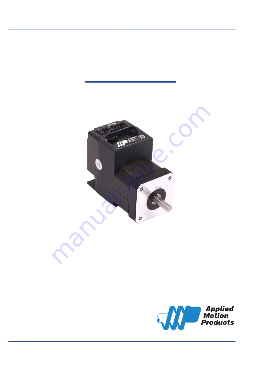
TSM17S/Q
Integrated Step-Servo Motor
Hardware Manual
920-0084C
8/2/2018
Страница 1: ...TSM17S Q Integrated Step Servo Motor Hardware Manual 920 0084C 8 2 2018 ...
Страница 2: ...SM17S Q Communications 14 3 2 1 Connecting to the PC using RS 232 14 3 2 2 Connecting to a Host using RS 485 15 3 3 Inputs and Outputs 17 3 3 1 Connector Pin Diagram 17 3 3 2 STEP DIR Digital Inputs 18 3 3 3 X3 X4 X5 X6 Digital Input 19 3 3 4 X7 X8 Digital Input 20 3 3 5 AIN Input 21 3 3 6 Programmable Output Y1 Y2 Y3 22 3 3 7 Programmable Output Y4 23 4 Troubleshooting 24 5 Reference Materials 25...
Страница 3: ... 8 2 2018 TSM17S Q Hardware Manual Model Communications RS 232 RS 485 Modbus RTU TSM17S 1AG TSM17S 1RG TSM17S 2AG TSM17S 2RG TSM17S 3AG TSM17S 3RG TSM17Q 1AG TSM17Q 1RG TSM17Q 2AG TSM17Q 2RG TSM17Q 3AG TSM17Q 3RG ...
Страница 4: ...gital input Control Velocity Analog velocity SCL Commanded Velocity Jogging Position Control Digital Signal type Step Direction CW CCW pulse Analog Position Serial Commanded Position Q Programming Q Verision only Stand alone operation Communications RS 232 RS 485 or Modbus RTU 5000 line 20 000 counts rev encoder feedback Available torque TSM17 1 G Up to 0 28N m Continuous 0 35 N m Boost TSM17 2 G ...
Страница 5: ... Voltage Temp Detect Over Current Detect motor encoder 5 Volt DC Power Supply DSP Driver Controller 3 3VDC Internal Logic Supply TSM17S Q I O Connector 5VDC 100mA max GND Status AIN Optical Iso RS 232 or RS 485 Comm Conn Power Conn GND 5V RS 232 RXD 5V TXD GND GND or RS 485 RX RX TX TX GND X1 X2 X3 X4 X5 X6 X7 X8 Y1 Y2 Y3 Y4 Optical ISO ...
Страница 6: ...t in injury and damage to persons and machinery All technical information concerning the installation requirements must be strictly adhered to It is vital to ensure that all system components are connected to earth ground Electrical safety is impossible without a low resistance earth connection This product contains electrostatically sensitive components that can be damaged by incorrect handling F...
Страница 7: ... Connect the drive to the PC using the programming cable When using RS 485 it must be setup in a 4 Wire configuration see Connecting to a host using RS 485 below Connect the drive to the power supply See instructions below Launch the software by clicking Start Programs Applied Motion Products Apply power to the drive The software will recognize the drive and display the model and firmware version ...
Страница 8: ...on Absolute minimum power supply input is 10 VDC If the Input supply drops below 10 VDC the low voltage alarm will be triggered This will not fault the drive Absolute maximum power supply input is 55 VDC at which point an over voltage alarm and fault will occur When using a power supply that is regulated and is near the drive maximum voltage of 55 VDC a voltage clamp may be required to prevent ove...
Страница 9: ... the motor voltage the less current will be required from the power supply It is important to note that the current draw is significantly different at higher speeds depending on the torque load to the motor Estimating how much current is necessary may require a good analysis of the load the motor will encounter 0 0 5 1 1 5 0 0 1 0 2 0 3 0 4 0 10 20 30 40 50 TSM17 1 G 12V Power Torque N m Speed RPS...
Страница 10: ...ue Boost Supply Current Full Load No Load 0 0 5 1 1 5 0 0 1 0 2 0 3 0 4 0 5 0 6 0 10 20 30 40 50 TSM17 2 G 12V Power Torque N m Speed RPS Amps Continuous Torque Boost Supply Current Full Load No Load 0 0 5 1 1 5 0 0 1 0 2 0 3 0 4 0 5 0 6 0 10 20 30 40 50 TSM17 2 G 24V Power Torque N m Speed RPS Amps Continuous Torque Boost Supply Current Full Load No Load ...
Страница 11: ...ue Boost Supply Current Full Load No Load 0 0 5 1 1 5 0 0 1 0 2 0 3 0 4 0 5 0 6 0 7 0 10 20 30 40 50 Torque N m Speed RPS TSM17 3 G 12V Power Amps Continuous Torque Boost Supply Current Full Load No Load 0 0 5 1 1 5 0 0 1 0 2 0 3 0 4 0 5 0 6 0 7 0 10 20 30 40 50 Torque N m Speed RPS TSM17 3 G 24V Power Amps Continuous Torque Boost Supply Current Full Load No Load ...
Страница 12: ...920 0084C 8 2 2018 TSM17S Q Hardware Manual 0 0 5 1 1 5 0 0 1 0 2 0 3 0 4 0 5 0 6 0 7 0 10 20 30 40 50 Torque N m Speed RPS TSM17 3 G 48V Power Amps Continuous Torque Boost Supply Current Full Load No Load ...
Страница 13: ...nternal fuse on the drive and void the warranty Applied Motion Products offers two matched power supplies for use with the TSM A 24VDC 150W P N PS150A24 and a 48VDC 320W P N PS320A48 These power supplies have current over load capability making them ideal for use To use with a switch power supplier a RC880 regen must be connected in system The RC880 regeneration clamp is for use where regeneration...
Страница 14: ...mmunication types to a PC 3 2 1 Connecting to the PC using RS 232 Locate the TSM17S Q within 2 5 meters of the PC Plug the DB9 connector of the communication cable that came with the drive into the serial port of the PC Plug the small end into the spring clamp style connector on the TSM17S Q Secure the cable to the PC with the screws on the DB9 connector Note If the PC does not have an RS 232 seri...
Страница 15: ... and receive wires One pair of wires must connect the host s transmit signals to each drive s RX and RX terminals The other pair connects the drive s TX and TX terminals to the host s receive signals A logic ground terminal is provided on each drive and can be used to keep all drives at the same ground potential This terminal connects internally to the DC power supply return V so if all the drives...
Страница 16: ...ve will need to connect individually to the host computer so that it can be assigned a unique address Once the drive has been connected to the PC as described above launch the Step Servo Quick Tuner software Apply power to the drive If a drive has already been configured click the Upload button so that the Step Servo Quick Tuner settings match those of the drive When operating the drive in SCL mod...
Страница 17: ...hen not being used for the Step Direction function these inputs can be used for CW CCW step or general purpose input X3 X4 are low speed software programmable input and can be used for Motor Enable Disable and Alarm Fault Reset function or general purpose input X5 X6 X7 X8 are low speed software programmable input and can be used for CW CCW Jog Speed 1 Speed 2 oscillator mode CW CCW Limit or gener...
Страница 18: ...ing to Indexer with Sinking Outputs TSM17 DIR COM STEP Indexer with Sourcing Outputs DIR DIR STEP STEP Connecting to Indexer with Sourcing Outputs TSM17 DIR DIR STEP DIR DIR STEP STEP STEP Indexer with Differential Outputs Connecting to Indexer with Differential Outputs Many high speed indexers have differential outputs TSM17 DIR DIR STEP STEP 5 24 volt DC Power Supply Using Mechanical Switches di...
Страница 19: ...und but not always In the case of the TSM17 drives if you are using sourcing PNP input signals then you will want to connect COM to ground power supply If you are using sinking NPN signals then COM must connect to power supply Note If current is flowing into or out of an input the logic state of that input is low or closed If no current is flowing or the input is not connected the logic state is h...
Страница 20: ...avel limit switches The diagrams below show how to connect the X7 X8 Inputs to various commonly used devices 5 24 volt DC Power Supply Connecting an NPN type Proximity Sensor to an Input when prox sensor activates input goes low X7 X8 X7 X8 NPN Proximity Sensor output TSM17 5 24 volt DC Power Supply Connecting a PNP type Proximity Sensor to an Input when prox sensor activates input goes low X7 X8 ...
Страница 21: ...r software to set the signal range offset dead band and filter frequency The TSM17S Q provides a 5 volt 100mA limit voltage supply that can be used to power external devices such as potentiometers It is not the most accurate supply for reference for more precise readings use an external supply that can provide the desired accuracy 5v AIN GND 100 mA limit Signal Conditioning inside drive r o t c e ...
Страница 22: ...position dynamic Y3 can be set to control a motor brake These outputs can also be turned on and off by program instructions like Set Output SO The output can be used to drive LEDs relays and the inputs of other electronic devices like PLCs and counters Diagrams of various connection types follow Do not connect the outputs to more than 30 volts The current through each output terminal must not exce...
Страница 23: ...tput frequency proportional to motor speed tach signal or to provide a timing output 50 pulses rev or to indicate whether the motor is in position static Diagrams of various connection types follow Do not connect the output to more than 30 volts The current through the output terminal must not exceed 100mA Y4 Y4 5 24 volt DC Power Supply Connecting a Sinking Output Load TSM17 COM IN Y4 Y4 PLC Conn...
Страница 24: ...or information on how to do this and which warnings may be masked Code Error solid green motor disabled flashing green motor enabled 1 red 1 green position limit 1 red 2 green drive disabled 2 red 1 green ccw limit 2 red 2 green cw limit 3 red 1 green over temperature 3 red 2 green internal voltage bad 3 red 3 green non volatile memory error 4 red 1 green over voltage 4 red 2 green under voltage 4...
Страница 25: ...ware Manual 5 Reference Materials 5 1 Mechanical Outlines Unit mm Model Length L Length M TSM17S Q 1 G 69 5 26 6 TSM17S Q 2 G 75 32 1 TSM17S Q 3 G 83 5 40 6 L 1 20 15 2 Ø22 M 5 5 Flat Ø6 31 31 42 3 Max 42 3 Max 43 5 74 61 4 M3 Depth 4 5 ...
Страница 26: ...odes of operation plus stored Q program execution Digital Inputs X1 X2 Optically isolated 5 24 volt Minimum pulse width 250 ns Maximum pulse frequency 2 MHz Function Pulse Direction CW CCW Pulse A B quadrature encoder following start stop direction oscillator mode or general purpose input X3 X4 Optically isolated 5 24 volt Minimum pulse width 100 μs Maximum pulse frequency 5 KHz Function Servo on ...
Страница 27: ...3 amp rating is boost 0 0 1 0 2 0 3 0 4 0 10 20 30 40 50 Torque N m Speed rps TSM17 1 G 12V 24V 48V 12V 24V 48V Continuous Boost 0 0 1 0 2 0 3 0 4 0 5 0 6 0 10 20 30 40 50 12V 24V 48V 12V 24V 48V TSM17 2 G Torque N m Speed rps Continuous Boost 0 0 1 0 2 0 3 0 4 0 5 0 6 0 7 0 10 20 30 40 50 12V 24V 48V 12V 24V 48V TSM17 3 G Torque N m Speed rps Continuous Boost ...
Страница 28: ...e software which drive is connected and what the firmware version is There are two types of SCL commands buffered and immediate Buffered commands are loaded into and then executed out of the drive s command buffer Buffered commands are executed one at a time and in sequential order The buffer can be filled with commands without the host controller needing to wait for a specific command to execute ...
Страница 29: ...ll adjust a drive s serial communications protocol to best fit an application Typically this command is used when configuring a drive and saved as part of the startup parameters But it can be used at any time to dynamically alter the serial communications The Host Command Reference contains the complete command listing as well as instructions on connecting and configuring the TSM23S Q for use in S...
Страница 30: ...ing switching power supplies P N PS150A24 150W 24VDC 11 5MAX 3 M4 L 4mm LED V ADJ CN3 9 1 2 3 4 5 6 7 25 117 28 12 5 25 44 170 152 65 45 4 M4 L 4mm 8 9 5 49 5 18 63 99 2 1 P N PS320A48 320W 48VDC 5 4 8 1 199 157 4 M4 L 4mm Air flow direction FAN 4MAX 18 11 5MAX 8 63 99 18 5 V ADJ CN3 LED 1 2 3 4 5 6 7 9 5 4 M4 L 4mm 12 5 25 130 52 25 12 5 ...
Страница 31: ...neration is transferred back to the power supply This can trip the overvoltage protection of a switching power supply causing it to shut down Applied Motion Products offers the RC880 regeneration clamp to solve this problem If in doubt use an RC880 for the first installation If the regen LED on the RC880 never flashes you don t need the clamp USB Serial Adapter P N 8500 003 USB to RS 232 P N 3004 ...
Страница 32: ...32 920 0084C 8 2 2018 TSM17S Q Hardware Manual Cables I O P N 3004 318 2M Included RS 485 and CANOpen P N 3004 313 1M Included ...
Страница 33: ... Power RS232 Connector 1615780000 Weidmuller Housing ZER 04V S JST I O Pin Connector SZE 002T P0 3 JST Housing PUDP 28V S JST RS 485 CANOpen Pin Connector SPUD 001T P0 5 JST Housing ZER 05V S JST Pin Connector SZE 002T P0 3 JST Connector 5452570 Housing PUDP 28V S Housing ZER 04V S ZER 05V S Pin connectors SPUD 001T P0 5 Pin conector SZE 002T P0 3 ...
Страница 34: ...34 920 0084C 8 2 2018 TSM17S Q Hardware Manual 6 Contacting Applied Motion Products 404 Westridge Dr Watsonville CA 95076 USA 1 800 525 1609 Tel 831 761 6555 www applied motion com ...