background image

5.  Operation Panel Switches in Operation Mode 

5.4  Handle/Incremental Feed Magnification Factor 


II

-16 

5.4  Handle/Incremental Feed Magnification Factor 


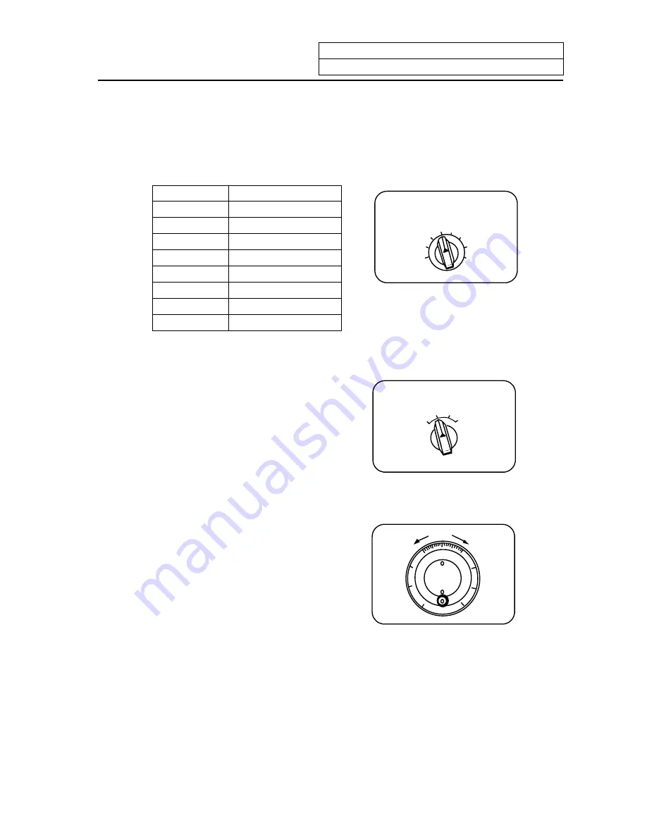
Use the HANDLE/INCREMENTAL MAGNIFICATION switch to set the travel distance specified when 
manual handle feed or incremental feed is made. 


The travel distances for each axis are listed below: 


(Up to 1000 can be set for handle feed.) 


 Handle


 Incremental


 1   

 10 


10 

 100 


100 

 1000 


1000 

 1    5000 

 10 

  10000 

 100 


50000 

 1000 


100000 


HANDLE/ 

INCREMENTL MAGNIFICATION 

10 

10000


1
1

100 
50000


1000 
100000


10
10

100
100

1000 
1000 

5000


5.5  Handle Feed Axis Selection 


Use the HANDLE FEED AXIS SELECT switch 
to select the axis moved by handle operation 
when the handle mode is selected. 


X

Y

HANDLE FEED AXIS SELECT 


5.6  Manual Pulse Generator 


In the manual handle mode, fine feed of the 
machine can be made by turning the manual 
pulse generator. 
The manual pulse generator has 100 
graduations per revolution and outputs one 
pulse per graduation. The travel distance per 
pulse is set by using the HANDLE/ 
INCREMENTAL MAGNIFICATION switch.


HANDLE 

00

+

-

10

10

7 2 


Содержание EZMotion-NC E60 Series

Страница 1: ......

Страница 2: ...ion MELDAS and MELSEC are registered trademarks of Mitsubishi Electric Corporation Other company and product names that appear in this manual are trademarks or registered trademarks of the respective company ...

Страница 3: ...NC E60 E68 Programming Manual M TYPE IB 1500174 ENG EZMotion NC E60 E68 Programming Manual L TYPE IB 1500173 ENG In this NC unit the machining programs parameters and tool compensation data are saved in the memory memory elements This NC unit s memory is backed up by lithium batteries and under normal conditions will last 6 years from the date of manufacture However data contents could be lost und...

Страница 4: ... CAUTION may lead to major results depending on the situation In any case important information that must always be observed is described DANGER Not applicable in this manual WARNING Not applicable in this manual CAUTION 1 Items related to product and manual For items described as Restrictions or Usable State in this manual the instruction manual issued by the machine maker takes precedence over t...

Страница 5: ...l of the various data in the NC memory is erased when formatting Be sure to use the transfer function to transfer all necessary data to another storage device before formatting Even if the tool compensation amount write command parameter write command or variable data write command is executed with graphic check the data will be actually written in and the original data will be overwritten To prev...

Страница 6: ...to an input output device and then replace the battery If the BATTERY alarm occurs the machining programs tool data and parameters may be damaged After replacing the battery reload each data item If the axis overruns or emits an abnormal noise immediately press the emergency stop button and stop the axis movement 8 Items related to maintenance Incorrect connections may damage the devices so connec...

Страница 7: ...ution Program Monitor 41 2 3 2 Execution Modal Monitor 42 2 3 3 Total Integrating Time Display 44 2 4 PROGRAM SEARCH 46 2 4 1 Memory Search 47 2 4 2 Tape Search 48 2 4 3 IC Card Search 50 2 4 4 Compare Stop 51 2 5 Resuming the Program 53 2 5 1 Operation Sequences for Program Restart 55 2 5 2 Restart Search Operations 58 2 5 3 Restart Position Return System 64 2 5 4 Manual Numeric Commands with Pro...

Страница 8: ... 1 1 Tool Offset Data Setting 111 3 1 2 Tool Offset Data Clear 111 3 1 3 Tool Offset Data Setting Modes Absolute and Incremental 111 3 1 4 Manual Tool Length Measurement 114 3 1 5 Manual Numeric Command Operation on the TOOL OFFSET Screen M T 117 3 2 Tool Registration 118 3 2 1 Function Outline 118 3 2 2 Tool Registration in Magazine Pot 119 3 2 3 Tool Registration in HEAD NEXT and INDEX 120 3 2 4...

Страница 9: ...5 3 3 Data Change 177 5 3 4 Data Insertion 178 5 3 5 Deletion of One Character 179 5 3 6 Deletion of One Block 180 5 3 7 Deletion of Data on One Screen 181 5 4 MDI Screen Extension Operation 182 5 4 1 MDI Data Registration in Memory 182 5 5 Edit Screen Extension Operation 183 5 5 1 Edit Data Call 183 5 5 2 New Program Registration and Preparation 188 5 6 PLAYBACK 189 5 6 1 Playback Operation 190 5...

Страница 10: ...ning Program Condense 247 6 4 3 Machining Program Merge 248 6 4 4 Changing the Machining Program Number 249 6 5 PROGRAM FILE 250 6 6 RS 232C I O Device Connection 251 6 6 1 Connection of Tape Reader Tape Puncher Printer FLD 251 6 7 Data Protection 252 6 7 1 Data Protection Key 252 6 7 2 Edit Lock B C 254 7 Diagnosis 256 7 1 ALARM MESSAGE 257 7 1 1 Tracing of Alarm and Stop Codes 257 7 2 SERVO MONI...

Страница 11: ...2 Device Monitor Screen 297 8 IC Card Operation 299 8 1 IC Data Screen 301 8 1 1 IC Card Input Output 301 8 1 2 File Selection Screen 303 8 1 3 NC Data File Name 305 8 1 4 IC Card I O Screen Operation 306 9 Graphics 314 9 1 Outline of Functions 314 9 2 Menu Function 315 9 3 Use of the Trace Mode 317 9 4 Use of the Check Modes 319 9 5 GRF MODE 328 9 6 SCALE 330 9 6 1 Changing the Scale 330 9 6 2 Ch...

Страница 12: ...4 6 Handle Feed Mode 12 4 7 Memory Mode 13 4 8 MDI Operation Mode 14 5 Operation Panel Switches in Operation Mode 15 5 1 Rapid Traverse Override 15 5 2 Cutting Feed Override 15 5 3 Manual Feedrate 15 5 4 Handle Incremental Feed Magnification Factor 16 5 5 Handle Feed Axis Selection 16 5 6 Manual Pulse Generator 16 5 7 Cycle Start and Feed Hold 17 5 8 Feed Axis Selection 17 6 Operation Panel Switch...

Страница 13: ...rameter Settings 6 3 Adjustment of Dog type Reference Point Return 7 3 1 Outline 7 3 2 Dog type Reference Point Return 7 3 3 Reference Point Return Parameters 9 3 4 Dog type Reference Point Return Adjustment Procedures 14 4 Absolute Position Detection System 15 4 1 Outline 15 4 2 Coordinate System of Absolute Position System 15 4 3 Starting up Absolute Position Detection System 16 5 Stored Stroke ...

Страница 14: ... APPENDIXES Appendix 1 List of Function Codes 1 Appendix 2 Table of Command Value Ranges 2 Appendix 3 Circular Cutting Radius Error 3 Appendix 4 Registering Editing the Fixed cycle Program 4 4 1 Fixed Cycle Operation Parameters 4 4 2 Inputting the Fixed Cycle Program 4 4 3 Outputting the Fixed Cycle Program 4 4 4 Erasing the Fixed Cycle Program 4 4 5 Standard Fixed Cycle Subprogram For L system 5 ...

Страница 15: ...I OPERATION SECTION ...

Страница 16: ...AN SHIFT INPUT CALC RESET READY Data correction keys Input key calculation Shift key Menu keys Reset key Cursor keys Setting keys READY LED Function selection keys Page keys Alphabetic character numerical character and symbol keys 2 Appearance of the Setting and Display Unit For E68 READY MONITOR TOOL PARAM EDIT MDI DIAGN IN OUT SFG F0 9 6 3 8 5 2 7 4 1 0 SP EOB DELETE INS C B CAN SHIFT INPUT CALC...

Страница 17: ...rea Operation status mode alarm display area Menu display area MONITOR 3 1 4 Maximum number of pages Page number Menu number Function name Menu 1 Menu 2 Menu 3 Menu 4 MENU ST1 ST2 ST3 ST4 ST5 ST6 ST7 ST8 Operation mode Operation status mode display and menu display during normal operation Menu 1 Menu 2 Menu 3 Menu 4 Menu 5 Alarm 1 19 characters Alarm message display during alarm occurrence Alarm 2...

Страница 18: ...bsolute command mode G90 INC Incremental command mode G91 ST4 This indicates that subprogram is not executed SB1 SB8 Machining program execution is controlled according to subprogram data Each value of 1 to 8 indicates the subprogram depth ST5 G54 G59 Selection of the workpiece coordinate system is indicated ST6 G40 Tool radius compensation cancel state G41 During tool R compensation left G42 Duri...

Страница 19: ... N1 N2 MONITOR 1 Blank screen Title screen SHIFT C B CAN Display screen 1 When the power is turned ON the Title screen is displayed To select a display screen on the Title screen press the corresponding function selection key 2 To select a blank screen on a display screen select the MONITOR 1 screen and press SHIFT key then C B CAN key To select a display screen on the blank screen press the corre...

Страница 20: ...000 2000 2200 3000 4000 5000 6000 7000 7000 The setting can be displayed when SETUP PARAM is selected EDIT MDI MDI EDIT MDI ENT PROGRAM SMALL LARGE FILE SEARCH DIAGN IN OUT SPINDLE MONITOR PLC I F ALARM MESSAGE SERVO MONITOR SERVO DIAGNOSIS ABS SERVO MONITOR ABS POSITION SET ERASE FILE INPUT OUTPUT SUPPORT Not used NC DATA SAMPLING NSK TERMINAL Not used AUX PRM AUX MON PLC TRACE ADJUST S ANALOG OP...

Страница 21: ...peration 1 3 Screen Transition Diagram I 6 SFG PROGRAM ERASE TRACE STEP OPERATION SEARCH ERASE CHECK STANDARD GRF MODE ROTATION SCALE F0 VISUAL ANALYZER LADDER MONITOR ON OFF PARAMETER 1222 2 ON OFF PARAMETER 6451 5 OFF and 6451 0 ...

Страница 22: ... CMP PLC TIMER 1000 9000 2000 2200 3000 4000 5000 6000 7000 7000 EDIT MDI MDI EDIT MDI ENT PROGRAM SMALL LARGE FILE SEARCH DIAGN IN OUT SPINDLE MONITOR PLC I F ALARM MESSAGE SERVO MONITOR SERVO DIAGNOSIS ABS SERVO MONITOR ABS POSITION SET SUPPORT Not used NC DATA SAMPLING NSK TERMINAL Not used AUX PRM AUX MON ERASE FILE INPUT OUTPUT PLC TRACE ADJUST S ANALOG OPERATION HISTORY CONFIG MENU 1 MENU 2 ...

Страница 23: ...ation 1 3 Screen Transition Diagram I 8 SFG PROGRAM ERASE TRACE STEP OPERATION SEARCH ERASE CHECK STANDARD RANGE GRF MODE ROTATION SCALE F0 VISUAL ANALYZER LADDER MONITOR ON OFF PARAMETER 1222 2 ON OFF PARAMETER 6451 5 OFF and 6451 0 ...

Страница 24: ...en MONI TOR TOOL PARAM EDIT MDI DIAGN IN OUT SFG F0 Press the function selection key corresponding to the function screen to be displayed Example Press the MONI TOR key 1 The previously displayed menu screen is displayed in the data display area 2 The first display screen after power is turned ON is the screen on the first menu If the same function selection key is again pressed a return is made t...

Страница 25: ...OCK O N N20 G91 G28X0 Y0 Z0 O N TAPE When the rightmost menu in the menu display area is MENU it indicates that other menus than the displayed menus exist Make menu change by pressing the menu key below MENU then select the menu screen to be displayed Press the MENU key POSI COORDI COMMAND SEARCH MENU 1 1 Only the menu display area is changed and the remaining menu group is displayed RESERCH PLC S...

Страница 26: ... 0 000 r 0 000 P 0 R r P Press the menu key again 2 T OFSET T DATA NOSE R LIFE MENU 1 The operation menu is displayed in the menu display area INPUT INPUT RETURN NOSE R TOOL 3 1 4 1 R 0 000 r 0 000 P 0 2 R 0 000 r 0 000 P 0 3 R 0 000 r 0 000 P 0 R r P 3 Select a page in the menu screen When the menu screen contains a number of pages feed pages by using the page key the rightmost page key NEXT is t...

Страница 27: ...or to the next parentheses press the key RESERCH PLC SW COM VAR LOC VAR MENU 104 DATA NAME 3 Press data keys Seeing the data display area contents enter new data by using the keys Example To change to 12 345 press 1 2 3 4 5 RESERCH PLC SW COM VAR LOC VAR MENU 104 DATA 12 345 NAME 4 Press the INPUT key Check the setup contents displayed in the setting area and set the data in memory by pressing the...

Страница 28: ...ng 2 When any key is pressed already displayed data is moved one column to the left and the data corresponding to the key pressed at the cursor position is displayed DATA 12 When 3 is pressed DATA 123 3 If a number of parentheses exist in the data setting area pressing the key when the cursor is in the right end within a parenthesis causes the cursor to move to the right end within the next pair W...

Страница 29: ...rrected Display is made in the setting area as shown in the right If you make successive four strokes of the key If you press 3 10 DATA 12 345 10 DATA 12 345 10 DATA 13 345 2 is corrected to 3 and the cursor is moved one column to the right If you press the key 10 DATA 13 345 The cursor is only moved one column to the right If you press 0 SP 0 SP 0 SP 10 DATA 13 000 The character at the cursor pos...

Страница 30: ...DATA 234 If you press the SHIFT key the cursor is moved to the right end within the following parentheses 3 Miscellaneous information 1 Data can also be set by other special methods See the appropriate items For example manual numeric command setting is performed by the reverse display setting method 2 If an invalid key is pressed when data is set within parentheses a setting error will occur at i...

Страница 31: ...reen Even if the parameter is set to 0 the screen can be turned OFF by pressing the SHIFT and C B CAN keys Note The screen will not be turned OFF even if the SHIFT and C B CAN keys are pressed on a screen other than the POSITION screen b Backlight OFF When the Screen Sever function works the backlight turns OFF 2 Turning the screen ON If a key is pressed or the screen display request signal is inp...

Страница 32: ...d an alphanumeric symbol or INPUT key is pressed the first key will be handled as that for turning the screen ON The key will not be input b If the function key menu key page key or system changeover key is pressed while the screen is OFF the screen corresponding to the pressed key will turn ON c The screen will not turn ON even if the reset key is pressed However if the screen display request sig...

Страница 33: ...Previous page key Next page key RESERCH PLC SW COM VAR LOC VAR MENU PROGRAM FILE SEARCH PROGRAM FILE SEARCH TIME COM VAR MODAL INFORM MONITOR menu display No 1 to 4 POSITION X M Y S Z T PREVIOUS PAGE NEXT PAGE MENU PLC SW COM VAR COORDI POSITION DIS TO GO WORK MACHINE COMMAND PROGRAM DISPLAY SEARCH PROGERAM FILE SEARCH MONITOR menu display No 5 to 8 PREVIOUS PAGE NEXT PAGE LOC VAR LOC VAR RESERCH ...

Страница 34: ... following can be performed on the POSITION screen 1 Full screen erase 2 Origin set The current value POSITION data of each axis can be set to 0 3 Manual numeric command Miscellaneous function output of M S T etc can be set through the screen Display item Explanation 12 14 13 27 The date and the time are displayed O12345678 N12345 12 The currently executing program number sequence number and block...

Страница 35: ...on Workpiece coordinate Current value B Tool reference position Tool nose position Relative value b Displayed by tool nose position Tool The relative of the relation value counter display contents and the parameters is as shown below 0 Relative value The compensation amount is considered according to 1287 ext23 bit4 5 contents 1221 aux 05 bit7 1 Current value B The counter of the POSITION screen c...

Страница 36: ...id only when 1123 origin is set to 0 Note2 Counter zero and origin zero are disabled in the current value B In the following operations the INPUT key has the counter zero function and the C B CAN key has the origin zero set zero function Press the address key X 1 The address indication corresponding to the key is highlighted Press the INPUT key counter zero or C B CAN key origin zero 1 The axis po...

Страница 37: ... causes the corresponding commanded value display section to be highlighted and makes the system ready for input of manual numeric command The spindle function key is S tool function key is T and miscellaneous function key is M 3 Key in the numerical value to be input 4 Press the INPUT key Example The procedures to execute S1200 by manual numeric command are given below First select POSITION displ...

Страница 38: ...ith pressing the address key corresponding to the command Press DELETE INS DELETE INS DELETE INS to delete the erroneously set numeric Example In this condition the numeric is desired to be replaced by S1500 S 1200 Method 1 S 1 Enter 5 0 0 S 1500 Press address key S to return to the initial status Method 2 S Enter 1 5 0 0 S 1500 4 Setting output range of manual numeric command The setting and outp...

Страница 39: ... the address key press any non numeric key If a manual numeric command address key such as M S T is pressed the previous operation will stop In this case the next manual numeric command sequentially begins If an axis address key X Y or Z etc is pressed the manual numeric command will stop In this case the origin zero or counter zero mode is then entered If the SHIFT C B CAN keys are pressed the ma...

Страница 40: ...rogram is displayed at the line of the next command 3 Displaying the operation program at branch to or at return from subprogram When a branch command M98 block is executed the subprogram is immediately displayed When a return command M99 block is executed the main program is immediately displayed 4 Difference between one block of work program and one execution block 1 A block containing only EOB ...

Страница 41: ... 0 50 100 80 T 1234 STP mm ABS G40 G54 MEMORY M 12 Display item Explanation O12345678 N12345 12 The currently executing program number sequence number and block number are displayed SUB O 1000 N 200 30 When a subprogram is being executed the program number sequence number and block number of the subprogram are displayed POSITION X 345 678 Y 345 678 Z 0 000 1 The current position during execution a...

Страница 42: ...to setting the parameters Note1 MST The spindle rotation speed command value is displayed The actual spindle rotation speed is shown in The tool command value is displayed The last four digits of the miscellaneous function command value are displayed POSITION B Tool nose position coordinate that is considered tool length offset and tool diameter compensation can be displayed in workpiece coordinat...

Страница 43: ...Display range 0 999999 Note1 The type of position counter to display can be selected with the base specification parameter 1137 Cntsel Counter Parameter 1137 Cntsel Left Right 00 or 10 MST 01 or 11 Next command 02 or 12 Current value B 03 or 13 Next command Manual interrupt amount 20 MST 21 Next command 22 Current value B 23 Current value B Manual interrupt amount 30 MST 31 Next command 32 Current...

Страница 44: ... Tape mode Machine control 2 Details a The next command can be corrected in the following two cases When single block stop is applied and there is a machining program containing a next command to be corrected During automatic operation there is an error program error in the next command s machining program and the program is stopped b During memory or MDI operation not only the displayed buffer da...

Страница 45: ...ffer correction area in normal state Display area When correcting the buffer the display changes so that the next command is displayed at the head of the area and the entire buffer correction area is highlighted The cursor will initially flicker at the head of the next command The cursor can be moved freely within the buffer correction area using the cursor keys 6 lines N123 S1230 M3 N124 G00 X68 ...

Страница 46: ...125 block the cause of the error is removed by correcting the buffer N121 G28 X0 Y0 N122 T1212 N123 S1230 M3 N124 G00 X68 Y201 N125 G01 X80 Y195 N126 Y150 N127 G02 X100 Y185 R20 N128 G01 X110 N129 G01 X120 N130 G01 X130 a Start automatic operation 1 A program error P62 will occur after N124 is executed N124 G00 X68 Y201 N125 G01 X80 Y195 N126 Y150 N127 G02 X100 Y185 R20 N128 G01 X110 N129 G01 X120...

Страница 47: ...50 at the end of the N125 line BUFFER EDIT P62 F CMD NOTHING N125 G01 X80 Y195 F50 N126 Y150 N127 G02 X100 Y185 R20 N128 G01 X110 N129 G01 X120 N130 G01 X130 d Press the INPUT key 1 The buffer correction will end when the INPUT key is pressed and the program being executed will display The buffer correction mode will be canceled 2 The message BUFFER EDIT will disappear 3 The program error P62 will...

Страница 48: ...yed and operated by feeding the page with the NEXT PAGE or PREVIOUS PAGE keys or by scrolling with the cursor keys The page feed and scrolling operations will be ignored Operation Buffer correction Program correction Scroll Not possible Possible Page feed return Not possible Possible Cursor movement Possible Possible Character replacement Possible Possible Character insertion Possible Possible Cha...

Страница 49: ...ert F50 at the end of the N125 line N125 G01 X80 Y195 F50 N126 Y150 N127 G02 X100 Y185 R20 N128 G01 X110 N129 G01 X120 N130 G01 X130 BUFFER EDIT Press the NEXT PAGE or PREVIOUS PAGE key 1 Return to the state when buffer correction is started N125 G01 X80 Y195 N126 Y150 N127 G02 X100 Y185 R20 N128 G01 X110 N129 G01 X120 N130 G01 X130 BUFFER EDIT Note1 The NEXT PAGE and PREVIOUS PAGE keys function t...

Страница 50: ...rection The M01 Operation alarm 0013 will occur e If there is no EOB in the last block edited when INPUT is pressed it will be added automatically N125 G01 X80 Y195 F50 N126 Y150 N127 G02 X100 Y185 R20 N128 G01 X110 N129 G01 X120 N130 G01 X130 BUFFER EDIT Press the INPUT key 1 is added to the end of the N130 block N124 G00 X68 Y201 N125 G01 X80 Y195 F50 N126 Y150 N127 G02 X100 Y185 R20 N128 G01 X1...

Страница 51: ...128 G01 X110 N129 G01 Y200 N130 G74 X120 0 Y100 0 Z 20 0 R 10 0 BUFFER EDIT Note Handling when entire block is not displayed The results will differ according to the state when INPUT key was pressed State Results EOB is not added to the end of displayed data The section P2 R0 not displayed will be the continuing part of the displayed section EOB is added to the end of the displayed data The sectio...

Страница 52: ...X150 0 Y150 0 I0 0 J25 0 N140 G02 X200 0 Y150 0 I25 0 J0 0 N150 G02 X200 0 Y200 0 I0 0 J25 0 N160 G02 X250 0 Y200 0 I25 0 J0 0 N170 G02 X250 0 Y250 0 I0 0 J25 0 N180 G02 X300 0 Y250 0 I25 0 J0 0 Press the key N130 G02 X150 0 Y150 0 I0 0 J25 0 N140 G02 X200 0 Y150 0 I25 0 J0 0 N150 G02 X200 0 Y200 0 I0 0 J25 0 N160 G02 X250 0 Y200 0 I25 0 J0 0 N170 G02 X250 0 Y250 0 I0 0 J25 0 N180 G02 X300 0 Y250 ...

Страница 53: ... Y150 0 I25 0 J0 0 N150 G02 X200 0 Y200 0 I0 0 J25 0 N160 G02 X250 0 Y200 0 I25 0 J0 0 N170 G02 X250 0 Y250 0 I0 0 J25 0 N175 G74 Z 10 0 R 5 0 P2 0 N180 G02 X300 0 Y250 0 I25 0 J0 0 h If an error occurs in the preread block and the buffer correction mode is entered the block in which the error occurred will appear at the head of the area i The error cannot be canceled for a fixed cycle or compound...

Страница 54: ...top with N110 Thus the buffer for N100 cannot be corrected If automatic start is executed when the block is stopped with N110 the N11 block will be executed and will stop with N12 Thus the buffer for N11 cannot be corrected Note that if the buffer is corrected when the block is stopped before N10 then N11 can be corrected Normal buffer correction of the subprogram s head is not possible as shown i...

Страница 55: ...EDIT LOCK C error will occur Note1 When either base specification parameter 1121 edlk_c or 1122 pglk_c is set the power must be rebooted Note2 Buffer correction is possible for the machining program program No 9000 to 9999 that is stored in either the IC card or tape even if edit lock C is valid c Data protection key Buffer correction is possible when data protection key 1 KEY1 Y238 is ON Buffer c...

Страница 56: ...xplanation O12345678 N12345 12 The currently executing program number sequence number and block number are displayed SUB O1000 N200 30 When a subprogram is being executed the program number sequence number and block number of the subprogram are displayed N10 N20 N30 N90 N100 The current program being executed is displayed The cursor is moved to the top of the current block being executed When prog...

Страница 57: ...13 1 G43 1 G54 1 P48 Tx 12 345 Tg 12 Tw 12 Tz 10 000 V 0 Tc 10 000 FA 24000 00 S 12345 M 12345678 FM 1200 00 10 FS 0 0000 T 1234 35 FE 0 0000 B 1234 40 N300 G1 X 100 000 Y12345 678 F2000 Display item Explanation O12345678 N12345 12 The currently executing program number sequence number and block number are displayed SUB O1000 N200 30 When a subprogram is being executed the program number sequence ...

Страница 58: ...ram command asynchronous feedrate modal value currently being executed is displayed mm min The manual feedrate is displayed mm min The program command synchronous feedrate modal value currently being executed is displayed mm rev The thread lead command synchronous feedrate modal value currently being executed is displayed mm rev The modal value of the current program command S being executed is di...

Страница 59: ...6 EXT TIME1 0 0 0 7 EXT TIME2 0 0 0 DATA Display item Explanation O12345678 N1234 12 The currently executing program number sequence number and block number are displayed SUB O1000 N200 30 When a subprogram is being executed the program number sequence number and block number of the subprogram are displayed 1 DATE 99 12 14 2 TIME 13 27 59 3 POWER ON 9999 59 59 4 AUTO OP 0 0 0 5 AUTO STL 0 0 0 6 EX...

Страница 60: ...l unit power ON to OFF AUTO OP Total integrating time of the work time from AUTO STL button pressing in the memory tape mode to M02 M30 or reset button pressing AUTO STL Total integrating time during automatic starting from AUTO STL button pressing in the memory tape mode or MDI to feed hold stop block stop or reset button pressing EXT TIME 1 Dependent on PLC sequence EXT TIME 2 Dependent on PLC s...

Страница 61: ...e number and block number are displayed SUB O 1000 N 200 30 When a subprogram is being executed the program number sequence number and block number of the subprogram are displayed PROGRAM FILE 100 1500 50000 1234567 200 2000 70000 2000000 300 3000 123456 3000000 400 7000 200000 4000000 1234 10000 300000 5000000 The numbers of the machining programs registered in memory are listed The numbers rangi...

Страница 62: ... Data in the found block is displayed in the work program display area Set the program number to be called Set the sequence number and block number as required Example To call O1234 N20 block O 1 2 3 4 N 2 0 COL TAPE 0 Note 1 If one of the following operations is executed in the EDIT screen after memory search the system enters a status in which nothing is being searched Operation is disabled at t...

Страница 63: ...mber in Set 1 in TAPE 2 Press the INPUT key Example O 1 0 N 1 COL TAPE 1 O 10 N 1 COL TAPE 1 SEARCH EXECUTION O 10 N 1 COL TAPE 1 PROGURAM SEARCH MONITOR 4 1 4 O 10 N 1 0 SUB O 0 N 0 0 PROGRAM FILE 100 200 300 400 1234 COLLATION BLOCK O N SEARCH COMPLETE O N COL TAPE 1 1 A search is started The paper tape reader operates and paper tape is run 2 During search the machining program data being read i...

Страница 64: ...for rewind code details Example When the tape was searched for N1 from a halfway position the tape end was reached before N1 was found When RWD SEARCH is ON N1G N2 N3 Position after rewind Search start position Tape rewind By pressing the INPUT key after rewind the tape is searched for N1 Error E03 NB NOT FOUND 5 If the target program number is not specified the tape will be searched for only N an...

Страница 65: ...mbers are displayed at O located at the top of the screen The data of the target block is displayed in the machining program s display area 3 Change the operation mode to the tape mode when operating Press the INPUT key Note Program Nos that are stored in the NC memory are displayed in PROGRAM FILE Supplements 1 Search from the files having the extension PRG in the IC card File name excluding the ...

Страница 66: ...the INPUT key The program No MDI for MDI sequence No block No and the message COLL EXEC will appear at COLLATION BLOCK The setting areas will change to blanks To execute compare stop with an MDI program set 0 zero for the program No O N COL TAPE COLLATION BLOCK COLL EXEC O 1234 N 20 3 Press the CYCLE START switch O N COL TAPE COLLATION BLOCK O N 1 Operation will start 2 When the designated block i...

Страница 67: ...t and the block number has not been set the block number is considered to be 0 5 Compare stop cannot be performed for blocks being executed or blocks already read into the preread buffer Compare stop can be set 6 Compare stop cannot be canceled if the block in which compare stop is set is being executed or has already been read into the preread buffer Cancellation of compare stop can be set 7 Even...

Страница 68: ...from the designated sequence number and block number Restart type 2 After machining program is stopped due to a halt and the power is turned OFF and ON machining is restarted from the designated sequence number and block number Restart type 3 T command restart After the machining program is stopped due to tool breakage etc the T command block executed last in the halted program is searched for and...

Страница 69: ...e searched the search block will be executed a multiple number of times when that subprogram is called for a similar number of times and so the number of times the block is to be executed is set here There is no need to set this when a one time execution is to be searched or when the search block is to be executed only once If 0 is set a one time execution is searched 0 This designates an unmodal ...

Страница 70: ...No cannot be input Upon completion of the restart search the M S T or B function restart distance to go and restart position are displayed RP is displayed when the axes have finished moving to the restart position and the subsequent axes do not move in either the or direction Move the axes to the restart return positions Refer to 2 5 3 Restart Position Return System Issue the M S T or B manual num...

Страница 71: ...nd Operations on PROGRAM RESTART screen For type A the program No cannot be omitted For type B the program No cannot be input Upon completion of the restart search the M S T and B functions the restart distance to go and the restart positions will be displayed RP is displayed when the axes have finished moving to the restart position and the subsequent axes do not move in either the or direction M...

Страница 72: ...on of the restart search the M S T or B function restart distance to go and restart position are displayed RP is displayed when the axes have finished moving to the restart position and the subsequent axes do not move in either the or direction Move the axes to the restart return positions Refer to 2 5 3 Restart Position Return System Issue the M S T or B manual numerical command Refer to 2 5 4 Ma...

Страница 73: ...0 P 1 T 1 M 0 PROGRAM RESTART MONITOR 5 1 2 O 1000 N 5 0 SUB O N RESTART G54 RESTART R X 130 000 X 150 000 Y 10 000 Y 150 000 Z 0 000 Z 0 000 C 0 000 C 0 000 N6 Y 70 N7 X 20 M MODE 0 MEMORY 1 TAPE 2 IC CARD T TYPE 0 UNMODLE 1 TYPE 1 2 TYPE 2 3 T TYP RESEARCH COMPLETE O N P T M The RESEARCH EXECUTION message appears during the search and upon its completion the RESEARCH COMPLETE message is displaye...

Страница 74: ... 2 O 1000 N 5 0 SUB O N RESTART G54 RESTART R X 130 000 X 150 000 Y 10 000 Y 150 000 Z 0 000 Z 0 000 C 0 000 C 0 000 N6 Y 70 N7 X 20 M MODE 0 MEMORY 1 TAPE 2 IC CARD T TYPE 0 UNMODLE 1 TYPE 1 2 TYPE 2 3 T TYP RESEARCH COMPLETE O N P T M The RESEARCH EXECUTION message appears during the search and upon its completion the RESEARCH COMPLETE message is displayed Assign the block at which machining is ...

Страница 75: ...s the INPUT key M MODE 0 MEMORY 1 TAPE 2 IC CARD T TYPE 0 UNMODLE 1 TYPE 1 2 TYPE 2 3 T TYP O 2000 N P T 0 M 0 M MODE 0 MEMORY 1 TAPE 2 IC CARD T TYPE 0 UNMODLE 1 TYPE 1 2 TYPE 2 3 T TYP SEARCH EXECUTION O 2000 N P T 0 M 0 PROGRAM RESTART MONITOR 5 1 2 O 2000 N 0 0 SUB O N RESTART G54 RESTART R X X Y Y Z Z C C O2000 N1 G91 G28X0 Y0 M MODE 0 MEMORY 1 TAPE 2 IC CARD T TYPE 0 UNMODLE 1 TYPE 1 2 TYPE ...

Страница 76: ...R 5 1 2 O 2000 N 0 0 SUB O 3000 N 0 0 RESTART G54 RESTART R X 80 000 X 80 000 Y 40 000 Y 40 000 Z 0 000 Z 0 000 C 0 000 C 0 000 O3000 N1 G42 G01 X 10 Y 10 D05 F100 M MODE 0 MEMORY 1 TAPE 2 IC CARD T TYPE 0 UNMODLE 1 TYPE 1 2 TYPE 2 3 T TYP RESEARCH COMPLETE O N P T M The RESEARCH EXECUTION message appears during the search and upon its completion the RESEARCH COMPLETE message is displayed Assign t...

Страница 77: ... M 0 PROGRAM RESTART MONITOR 5 1 2 O 2000 N 0 0 SUB O 3000 N 0 0 RESTART G54 RESTART R X 80 000 X 80 000 Y 40 000 Y 40 000 Z 0 000 Z 0 000 C 0 000 C 0 000 O3000 N1 G42 G01 X 10 Y 10 D05 F100 M MODE 0 MEMORY 1 TAPE 2 IC CARD T TYPE 0 UNMODLE 1 TYPE 1 2 TYPE 2 3 T TYP RESEARCH COMPLETE O N P T M The RESEARCH EXECUTION message appears during the search and upon its completion the RESEARCH COMPLETE me...

Страница 78: ...ccur and then search Set 3 in TYPE T in the setting area O N P T 3 M 1 The data set in the setting areas other than T and M will be ignored 2 Designate 1 in M for tape search M MODE 0 MEMORY 1 TAPE 2 IC CARD T TYPE 0 UNMODLE 1 TYPE 1 2 TYPE 2 3 T TYP O N P T 3 M 0 M MODE 0 MEMORY 1 TAPE 2 IC CARD T TYPE 0 UNMODLE 1 TYPE 1 2 TYPE 2 3 T TYP RESEARCH EXECUTION O N P T 3 M 0 PROGRAM RESTART MONITOR 5 ...

Страница 79: ...tart position return axis is a machine lock axis an operation error 0126 will occur Release the machine lock before starting the return to the restart position 2 Automatic restart position return If the program restart automatic return 1302 AutoRP is set to 1 and the cycle is started the axes will return to the restart position with dry run in the order designated with the restart position return ...

Страница 80: ...ged by setting the parameters Even if the miscellaneous function M is designated in the same block these will appear in the commanded order Press the INPUT key T SELECT T 10 S SPEED S1 3000 S SPEED S2 2nd AUX B AUX M 6 3 8 9 6 T SELECT T 10 S SPEED S1 3000 S SPEED S2 2nd AUX B AUX M 6 3 8 9 6 1 The command value with the cursor and the command name display now change to a highlighted display 2 The...

Страница 81: ...RO SINGLE control parameter ON and then proceed However the tool path may change because of the relationship of the radius compensation corner rounding chamfering and geometric read ahead blocks 8 When conducting restart with a tape operation it will not be possible to return to the proper machining start position if operation is started midway through the tape 9 Control command or external output...

Страница 82: ...carried out in the IC card operation If specified the setting operation error E13 occurs Also if unmodal search is carried out with type B the setting operation error E14 occurs 21 In the tape operation IC card operation if reset is performed after restart search type1 is executed and then restart search is executed again the setting operation error E81 and the program error P460 are displayed and...

Страница 83: ...eration Set the number of the switch to be set to ON in and press the INPUT key The mark of the switch is set to the up position In this state the switch function becomes effective and is controlled To set OPTIONAL STOP to ON Set 4 in Press the INPUT key RESERCH PLC SW COM VAR LOC VAR MENU PLC SWITCH PARAM 6 1 2 1 AUTO RESTART 9 2 BLOCK DELETE 10 AUTO POWER OFF 3 MANUAL ABS 11 4 OPTIONAL STOP 12 5...

Страница 84: ...2 103 113 104 114 105 115 106 116 107 117 108 118 109 119 DATA NAME Display item Explanation 100 123456 7890 101 12 3456 102 The variable numbers and contents are displayed If variable data is null Note the data display field will be blank If the number of columns of data is too large the data contains more than six characters in the integer part or more than four characters in the fraction part t...

Страница 85: ...d Variable name setting and reference commands require the user macro specifications and are limited to 20 common variables 500 519 The variable name is a string of up to seven alphanumeric characters beginning with an alphabetic character For common variables 500 519 the variable numbers data and variable names are displayed as shown below 500 123456 7890 ABCDEFG 501 100 0000 502 999 9000 Example...

Страница 86: ...when the INPUT key is first pressed the screen is changed to the page corresponding to the setup variable number If again the INPUT key is pressed the data or variable name is set and displayed at the position of the corresponding variable number 5 Whenever the or key is pressed for the variable number displayed in the variable number can be incremented or decremented by one 2 7 3 Common Variable ...

Страница 87: ...splayed The alphabetic character preceding each local variable number is argument code None of G L N O and P can be used as arguments and are displayed 33 local variables 1 to 33 exist for each user macro subprogram call level of depth If variable data is null Note the data display field will be blank If the number of columns of data is too large the data contains more than six characters in the i...

Страница 88: ...d when command is programmed with 3003 bit 0 set to 1 indicating that block stop is invalid MST FIN Is displayed when command is programmed with 3003 bit 1 set to 1 indicating the state of proceeding to the next block without waiting for the M S T command completion signal 2 8 1 Local Variable Data Display 1 When local variable 1 33 command exists in user macro or argument specification is made in...

Страница 89: ...level 1 17 33 Display level 2 17 33 Display level 3 17 33 Display level 4 17 33 Display level 2 1 10 0000 2 20 0000 3 30 0000 16 Display level 3 1 100 0000 2 200 0000 3 16 Display level 4 1 1000 0000 2 2000 0000 3 16 Main Level 0 01 Macro Level 1 010 Macro Level 2 0100 Macro Level 3 01000 Macro Level 4 Display level 1 1 1 0000 2 2 0000 3 3 0000 16 3 A local variable display page is selected by usi...

Страница 90: ...I O PAR SETUP MENU TLM BARRIER AXIS PREVIOUS PAGE NEXT PAGE TOOL menu No 1 to 4 PREVIOUS PAGE NEXT PAGE PARAM menu No 1 to 4 TOOL TIP OFFSET 1 to 10 TOOL DATA 1 to 10 NOSE R 1 to 10 TOOL LIFE DATA 1 10 to to to to WORK PROCESS I O BASE PARAM SETUP PARAMETER CONTROL PARAM PARAM PARAM PARAM Refer to PARAMETERS MENU CAUTION If a tool offset or workpiece coordinate system offset is changed during auto...

Страница 91: ... tool nose wear for each tool used When the tool compensation No is designated by the tool command T command compensation is carried out matching the tool length of the next screen X axis offset X axis tool length offset X axis wear offset Z axis offset Z axis tool length offset Z axis wear offset C axis offset additional axis C axis tool length offset C axis wear offset Data Function X X axis too...

Страница 92: ...en the INPUT key is first pressed The offset memory is displayed when the INPUT key is pressed again 4 By pressing the and keys the offset memory No displayed in can be continuously incremented or decremented by one 5 Tool offset data setting range Screen Item Function 1003 iunit Setting range unit B 999 999 mm TOOL TIP OFFSET X Z C Tool wear C 99 9999 mm B 9999 999 mm TOOL DATA X Z C Tool length ...

Страница 93: ...Example Incremental absolute value setting Setting Display Incremental value setting 2 0 1 2 X 100 100 Absolute value setting 2 100 1 2 X 100 100 Display 2 X 100 000 1 Mode selection method 1136 0 a Change over to the incremental value setting mode Set I in then press the INPUT key I X Z TOOL DATA I INC A ABS 1 INC is highlighted and the mode becomes the incremental value setting mode b Change ove...

Страница 94: ...lected once Mark of the screen selection menu indicates that the operation menu exist on the screen being displayed The operation menu is invalid during the tool measurement with manual tool length measurement function The operation menu during the tool measurement operates as follows 1 When the screen select menu is displayed INPUT INPUT don t appear during the tool measurement If INPUT INPUT wit...

Страница 95: ...ic position of each tool used When the tool compensation No is designated by the tool command T command compensation is carried out matching the wear data of the previous screen Generally the program basic point position is either the turret center position or the basic tool nose position 1 Turret center position Data Function X X axis tool length offset Z Z axis tool length offset C Additional ax...

Страница 96: ...workpiece Measure its dimensions and obtain the tool length from the measured values Workpiece Measurement basic point Measurement value The measurement basic point is characteristic for each machine the center of the chuck face etc Note The tool length from tool length measurement I is as follows depending on the whether the 1st reference point coordinate values have been set If the 1st reference...

Страница 97: ...lue Measurement point tlml The expression above is used for automatic calculation in the basic point method When the tool nose is placed on the measuring point the distance from the tool nose to the tool length basic point is calculated Z axis tool length X axis tool length Tool nose Tool length basic point Measuring procedure for the basic point method 1 Select the TOOL DATA screen 2 Set the tool...

Страница 98: ...m that the data has been written to X and Z of tool No 1 Repeat the above steps for each tool 1 X 12 350 Z 10 100 2 X 0 000 Z 0 000 3 X 0 000 Z 0 000 2 X Z Note 3 Incremented The reversed character returns to usual display Note 1 If the screen is changed back to the TOOL DATA screen after axis selection after the characters are highlighted the selection is invalidated the characters are not highli...

Страница 99: ...ter 2015 tlml beforehand Note Always set the measurement basic point with the radius regardless of the diameter radius command Set the measurement basic point in the machine coordinate system Measurement basic point X axis measurement value X axis tlml Measurement basic point Z axis tlml Z axis measurement value Tool length Machine value Measurement basic point tlml Measurement value The expressio...

Страница 100: ...key of the axis to be measured TOOL DATA TOOL 2 1 4 MACHINE X 212 350 I INC A ABS Y 210 100 1 X 0 000 Z 0 000 2 X 0 000 Z 0 000 3 X 0 000 Z 0 000 T M 1 X Z Example Select tool length No 1 X axis measurement X In this way the machine coordinate values of the measured axis are stored in the memory They are canceled by pressing the same key twice Also repeat steps 3 and 4 for the Z axis X axis measur...

Страница 101: ...the characters are highlighted the characters will return to the usual display Retry processing beginning with step 3 or 4 Note 2 If an axis having an error reference point return incomplete axis etc is selected the characters will not be highlighted An error message will appear Note 3 For a diameter command the diameter value is written For a radius command the radius value is written Note 4 An e...

Страница 102: ...commands Press the INPUT key The mode changes to the manual numerical command mode T M DATA 1 The data in the setting area is cleared and the cursor disappears from the screen 2 Executing the manual numeric command Carry out this step after 1 above 1 Press the address key corresponding to the command The display area of the corresponding command value is highlighted and a manual numeric command in...

Страница 103: ...t surface Z axis X axis Program basic position 1 Measurement method 1 Set the machine coordinate values of the touch sensor s contact surface in the parameters beforehand as the measurement basic value 2 Select the tool for which the tool compensation amount is to be measured 3 Using manual feed contact the nose of the tool against the touch sensor The tool compensation amount will be calculated f...

Страница 104: ...et Workpiece 1 Setting method 1 Select the tool and cut the workpiece edge 2 When the workpiece measurement signal is input the Z axis external workpiece coordinate offset data will be calculated from the machine coordinate value the length of the tool used and the tool nose wear compensation amount This value will be saved in the memory 2 No of set axes The external workpiece coordinate offset fo...

Страница 105: ...of the tool to be measured in the R register Tool No R2970 Wear data compensation No R186 Set the compensation No of the tool to be used for cutting in the R register The tool length offset amount is automatically calculated from the contacted position and is stored in the tool compensation amount memory Tool compensation amount Machine coordinate value Measurement basic value Sensor position The ...

Страница 106: ...ition Axis specification parameter p 2 Zp Xp Zm Z axis Xm X axis Xm X axis sensor machine coordinate value position measured by moving in direction 2015 tlml X axis Zm Z axis sensor machine coordinate value position measured by moving in direction 2015 tlml Z axis Xp X axis sensor machine coordinate value position measured by moving in direction 2016 tlml X axis Zp Z axis sensor machine coordinate...

Страница 107: ...on so measure the tool compensation amount one axis at a time The direction of the axis movement when the sensor contacts the tool will be output to R90 R290 Details of automatic calculation expression The tool compensation amount is automatically calculated with the following expression Tool compensation amount Machine coordinate value Measurement basic value Z axis X axis tool compensation amoun...

Страница 108: ... Notes 1 Do not move the tool in the Z axis direction after cutting the workpiece edges 2 If the edges do not need to be cut position to the measurement position 6 Set the Z axis external workpiece offset data with the workpiece measurement signal input Turn ON the workpiece measurement signal The Z axis external workpiece coordinate offset data will be automatically calculated from the machine va...

Страница 109: ...it4 Tool number selection Specify the R register that contains the tool number used for automatic calculation when measuring the coordinate offset of an external work piece 0 Conforms to 1130 set_t 1 Uses the tool number indicated by user PLC 7 Turn the tool measurement mode signal OFF This completes the measurement of the external workpiece coordinate offset When carrying out this operation indep...

Страница 110: ...00 P 3 R r P Set the tool nose radius R nose R wear r and tool nose point for each tool used When the tool nose R compensation G41 G42 G46 command is given the tool nose is assumed to be a half circular arc with radius R R r corresponding to the tool No Compensation is then carried out so that the half circular arc contacts the designated machining program path Data Function P0 to P8 Tool nose poi...

Страница 111: ...a tool life expiration signal X20E is output to the user PLC and the tool No is highlighted on the TOOL LIFE DATA screen Tool life management is possible for up to 80 tools tool Nos 1 to 80 This function is useful for setting tool abrasion and wear data and for knowing when to replace tools with new ones etc Item Details Setting range USED The cumulative time the tool is used This timer value is i...

Страница 112: ...life count for the commanded tool when a tool selection command is executed a warning is output to the user PLC When the count exceeds the service life count when the cutting feed starts after a tool selection command the corresponding tool No on the TOOL LIFE DATA screen is highlighted 3 Tool life management by time and count The tool life is managed simultaneously by time and count If the usage ...

Страница 113: ...l the displayed tool life management data time used time max count used count max can be set to 0 by pressing the SHIFT key and then pressing the C B CAN key and INPUT key Note If any other key has been pressed before the INPUT key is pressed the tool life management data will not be erased 3 4 5 Precautions 1 The cumulative time count is incremented even if the service lifetime service count is s...

Страница 114: ...9999 2 11 12345 11 000999 3 4 444444 4 999999 2 12 123456 12 123456 1 5 555555 5 999999 2 13 234567 13 000000 0 6 666666 6 999999 2 14 345678 14 000000 0 7 777777 7 999999 2 15 999999 15 000000 0 8 888888 8 999999 2 16 12 DATA 123456 12 123456 1 Note The MIN display following LIFE or USED will change according the method setting FORM 0 Time MIN Indicates that the data is displayed in minute units ...

Страница 115: ...ccording to the specifications USED When the designated tool is other than a not used tool the initial incrementation value can be adjusted by setting the USED data If no data is set this value becomes 0 Can be omitted ST Designate whether the tool is a tool skip tool or not Can be omitted If the data is not set or if 0 to 2 is set the data will be automatically set according to the relation with ...

Страница 116: ...1 4 24 24 100 2 5 5 5 0 0 5 25 25 100 2 6 6 6 0 0 6 26 26 100 2 7 7 7 0 0 7 27 27 100 2 8 8 8 0 0 8 28 28 100 2 DATA T OFSET T DATA NOSE R LIFE MENU LIFE 2 1 2 3 1 2 3 4 5 6 7 8 The LIFE management information of 2 groups in 1 screen TOOL LIFE TOOL 4 1 7 GROUP 1 FORM 0 LIFE 100 MIN GROUP FORM 1 LIFE 100 MIN TOOLNo CMP No USED MIN ST TOOLNo CMP No USED SET ST 1 1 1 100 2 1 21 21 100 2 2 2 2 0 3 2 2...

Страница 117: ... tool tool being used 2 Normal life reached tool 3 Tool skip tool TOTAL For tools using multiple compensation Nos the total of the usage data for each compensation No appears here If there is only one compensation No the data will be the same as USED GROUP LIST All registered group Nos appear here A highlighted group No indicates that the lives of all tools registered in that group have been reach...

Страница 118: ...ented Note The max life value is 999999 times If only the compensation No for the current tool changes the count is not incremented If the T code of the current tool is 12345678 T 1 2 3 4 5 6 7 8 Compensation No The count is not incremented even if this changes Tool No The count is incremented when this changes The count for group 01 is 1 time Note The count is for one program execution If the pro...

Страница 119: ... the tool The total of the currently selected tool s USED data appears in TOTAL of the CHOSEN TOOL column on Page 1 Example of the screen display when using multiple compensation Nos Time method life 100000 min Count method life 100000 times The life of tool 101010 is the total count of 1 to 3 The life of tool 101010 is the total usage time of 1 to 3 TOOL No CMP No USED MIN ST 1 101010 1 40000 2 2...

Страница 120: ...er PLC 4 Tools can be registered in USAGE on the upper portion of the screen The displayed name and displayed No can be changed 5 The No of tool registrations differs according to the specifications but a max of 80 tools can be registered with a max of 4 digits in the tool Nos 6 Tools can be selected by a manual numeric command T OFSET T DATA NOSE R LIFE MENU T REGISTRATION TOOL 2 1 2 HEAD NEXT 1 ...

Страница 121: ...d purpose of the data in D 3 6 3 Tool Registration in the Spindle Standby and Indexing Areas These commands are used to change the display data when the tool No set in the magazine pot differs with the displayed tool No Press the INPUT key Set N0 in MG and 8 in TOOL Set to USAGE MG N0 TOOL T OFSET T DATA NOSE R LIFE MENU T REGISTRATION TOOL 2 1 2 HEAD NEXT 1 NEXT 2 NEXT 3 SEARCH 10 20 21 30 22 MG ...

Страница 122: ...the manual numeric command mode M and T commands can be executed by screen operation in the manual numeric command mode 1 Changing from the normal data setting mode to the manual numeric command mode A cursor appears in the data setting area in the normal data setting mode but a cursor does not appear in the manual numeric command mode Confirm that the mode has changed over by checking this differ...

Страница 123: ...cellaneous function commands with M 2 Key input the numerical value to be commanded 3 Press the INPUT key The command is executed Note The manual numeric command operation is the same as the operation on the POSITION screen Refer to the section on manual numeric commands for the MONITOR and POSITION screens for details 3 Operation for returning the mode from the manual numeric command mode to the ...

Страница 124: ...TERS 1 to 40 or 11 to 20 MG 61 to MG 80 MG 41 to MG 60 MG 21 to MG 40 TOOL DATA TOOL DATA PARAM menu display No 1 to 4 TOOL menu display No 1 to 4 OFFSET REGIST LIFE MENU Menu selection keys Previous page key Next page key WORK PROCESS I O PAR SETUP MENU PREVIOUS PAGE NEXT PAGE PARAM menu No 1 to 4 PREVIOUS PAGE NEXT PAGE PARAM PARAM PARAM MENU TLM CAUTION If a tool offset or workpiece coordinate ...

Страница 125: ... REGIST LIFE NEMU TOOL OFFSET TOOL 1 1 2 A ABS I INC MACHINE Z 0 000 SURFACE 0 50 000 LENG WEAR RADIUS WEAR 1 120 000 0 020 50 000 0 099 2 100 000 0 004 30 000 0 000 3 100 000 0 000 60 000 0 010 4 20 000 0 005 150 000 0 008 5 20 000 0 530 150 000 0 059 6 300 000 0 032 50 000 0 111 7 250 000 0 000 50 000 0 000 8 150 000 0 006 80 000 0 009 9 200 000 0 000 150 000 0 003 10 500 000 0 667 100 000 0 888...

Страница 126: ...splayed 5 The offset memory number displayed in can be consecutively incremented or decreased by one by pressing the or key 6 To set the incremental mode enter in then press the INPUT key In incremental mode the set data is added to the data indicated in the display area To cancel the incremental mode enter A in then press the INPUT key the absolute mode is set For details see Sections 3 1 3 3 1 2...

Страница 127: ...o the incremental value setting mode as follows TOOL OFFSET A ABS I INC Enter I in then press the INPUT key I DATA I INC is displayed in reverse video indicating that the incremental value setting mode is valid Example of setting tool offset data in incremental value setting mode Radius comp Incremental 2 0 value setting Length comp 40 0 Old New Radius comp 5 0 Length comp Incremental value settin...

Страница 128: ... screens are selected once Mark of the screen selection menu indicates that the operation menu exist on the screen being displayed The operation menu is invalid during the tool measurement with manual tool length measurement function The operation menu during the tool measurement operates as follows 1 When the screen select menu is displayed INPUT INPUT don t appear during the tool measurement If ...

Страница 129: ...ool tip to measurement point workpiece top end can be measured and set as tool offset data When TLM basic length 1102 tlm 0 and SURFACE 0 0 are set tool length measurement I mode is set Machine coordinate zero point Workpiece Table Manual travel distance tool length offset data 2 Tool length measurement II When the tool is placed in the machine coordinate zero point the distance from the reference...

Страница 130: ...mode Turn ON the machine operation board TLM switch Move the tool to the measurement point by making jog feed or manual handle feed Upon completion of measurement specify the tool offset number Select the TOOL OFFSET screen Enter A in then press the INPUT key A ABS is displayed in reverse video To message TLM is displayed on the TOOL OFFSET screen 0 is displayed in DATA field The measurement value...

Страница 131: ...n parameter 2015 tlml data of machine parameter Set the value of the distance from the reference point to table surface Set 0 DATA and press the INPUT key The data is displayed in SURFACE 0 The message TLM is displayed on the TOOL OFFSET screen Dummy tool length data parameter tlml 0 is displayed in the DATA field The measurement value is displayed in the DATA field in sequence The current value o...

Страница 132: ...cessary regardless of the command M T Press the INPUT key The mode changes to manual numerical command T M DATA 1 Data is cleared from the setting field The cursor is also cleared from the screen 2 Execution the manual numeric command Execute this after operation 1 above 1 Press the address key corresponding to the command The corresponding command value display field is highlighted and the manual...

Страница 133: ...LC 4 Tools can be registered under HEAD NEXT 1 to NEXT 3 and INDEX displayed on the screen top The display names and the number of display pieces can also be changed 5 Although the number of registered tools varies depending on the specifications a maximum of 80 tools can be registered the maximum number of digits of a tool number is four 6 Tool selection and head replacement can be made by using ...

Страница 134: ... 24 The tool number and data in D are displayed in the specified magazine number area The magazine number in setting area MG is incremented by one and the data in other parenthesis pairs disappears If a number other than magazine numbers listed in the data display area is set the screen is changed to the screen corresponding to the setup magazine number when the INPUT key is first pressed When the...

Страница 135: ... 21 301 0 2 102 0 12 202 0 22 302 0 3 103 0 13 203 0 23 303 0 4 104 0 14 204 0 24 304 0 5 105 0 15 205 0 25 305 0 6 106 0 16 206 0 26 306 0 7 107 0 17 207 0 27 307 0 8 108 0 18 208 0 28 308 0 9 109 0 19 209 0 29 309 0 10 110 0 20 210 0 30 310 0 T 0 M MG TOOL D AUX 8 is displayed below HEAD in the data display area and a change is made to MG N1 in the data setting area Note Although the title displ...

Страница 136: ... is necessary regardless of the command M T Press the INPUT key The mode changes to manual numerical command T M MG TOOL D AUX 1 Data is cleared from the setting field The cursor is also cleared from the screen 2 Execution of the manual numeric command Execute this after operation 1 above 1 Press the address key corresponding to the command The corresponding command value display field is highligh...

Страница 137: ...ted parameters Items Details Setting range unit 1103 T_Life Validate life management Select the usage of the tool life management function 0 Do not use 1 Perform tool life management control 1104 T_Com2 Tool command method 2 Select the command method for when 1103 T_Life is set to 1 0 Handle the program tool command as the group No 1 Handle the program tool command as the tool No 0 1 1105 T_sel2 T...

Страница 138: ... 9000000 100000002000000030000000 40000000 50000000 60000000 70000000 80000000 90000000 Display item Explanation HEAD NEXT The tool numbers and TOOL LIFE data of the tools in HEAD and NEXT are displayed When TOOL LIFE is ineffective only the tool numbers are displayed GROUP LIST The group numbers registered as TOOL LIFE data are displayed A maximum of 90 group numbers are displayed on one screen I...

Страница 139: ...FFSET REGIST LIFE MENU Display item Explanation Setting range GROUP Group number of the tools which carry out tool life control A tool having the same group number is handled as a spare tool 1 to 99999999 1 to 10 These are data setting numbers not magazine pot numbers TOOL NO Number given to each tool The maximum number of tools that can be registered depends on the specifications This is a number...

Страница 140: ...d command G01 G02 G03 etc However rapid traverse feed or cutting feed commands inducing no movement are ignored G00 G01 G04 G00 G00 G01 G04 G01 Cutting feed Increment by 1 Cutting feed Increment by 1 b Tool diameter compensation data format 0 Compensation number Compensation data in tool data is handled as compensation number It is replaced with the compensation number commanded in a work program ...

Страница 141: ...5535 LIFE Life of each tool It is displayed in the use time minutes mount count the number of times the tool has been mounted on the spindle or work count the number of times hole drilling has been performed as specified in FORM If it is set to 0 life infinity is specified Use time 0 to 4000 min Mount count 0 to 9999 65000 times Work count 0 to 9999 65000 times USE Use data of each tool is display...

Страница 142: ...MENU Set necessary data of TOOL NO to USED in the corresponding parenthesis pairs in the ascending order of the numbers then press the INPUT key Set G in then press the INPUT key 2 Data registration Select TOOL LIFE data screen for the group in which data is to be registered OFFSET REGIST LIFE MENU TOOL LIFE TOOL 4 2 2 GROUP 123 TOOL NO ST FROM L CMP R CMP AUX LIFE USED 1 5678 4 220 45 678 50 000 ...

Страница 143: ...ata in given parenthesis pairs of the setting area then press the INPUT key 3 After setting the number is incremented by one and is set in setting area 4 To change data under number not displayed on the screen change the screen by using the NEXT PAGE or PREVIOUS PAGE key or setting the number in setting area 5 By changing a registered tool number to 0 the tool can be deleted 4 Deletion in group un...

Страница 144: ...S CONTROL PARAM PARAM PARAM PARAM WORK PROCESS I O PAR SETUP MENU Menu selection keys Previous page key Next page key TOOL menu display No 1 to 4 PARAM menu display No 1 to 4 WEAR DATA TOOL LENGTH DATA TOOL NOSE DATA TOOL LIFE DATA MENU PARAM menu No 1 to 4 L system TOOL menu No 1 to 4 M system TOOL menu No 1 to 4 MG61 to MG80 MG41 to MG60 MG21 to MG40 T REGISTRATION MG1 to MG20 to 21 to 40 or 11 ...

Страница 145: ... 0 000 57 G57 0 000 0 000 0 000 58 G58 0 000 0 000 0 000 59 G59 0 000 0 000 0 000 60 EXIT 0 000 0 000 0 000 DATA WORK PROCESS I O PAR SETUP MENU When workpiece position measurement specifications are added M system WORK OFFSET TOOL 5 1 18 A ABS I INC X Y Z C MACHINE 1 234 10 987 5 000 0 000 TLM 0 000 0 000 0 000 0 000 54 G54 0 000 0 000 0 000 0 000 55 G55 0 000 0 000 0 000 0 000 56 G56 0 000 0 000...

Страница 146: ...urement or the width center workpiece offset Measurement is set Then TLM P A is highlighted If the measurements switch ON or workpiece coordinate is set the coordinates value of measured position is cleared to 0 2 TLM P B M system The coordinate value of the measured position X Y of the first point of he hole center workpiece offset Measurement or the width center workpiece offset Measurement is s...

Страница 147: ...PUT key puts the setting mode to the incremental mode Data entered in the incremental mode is added to the data in the setting field Typing A in and pressing the INPUT key cancels the incremental mode and restores the absolute mode 4 1 2 Setting External Workpiece Coordinate System Offset Data By measuring the coordinate system deviation with an external touch sensor etc all workpiece coordinate s...

Страница 148: ...g area on the screen 2 Operation procedures Start a Returning to zero point Confirmation of tool length and nose wear b Selecting the tool c Positioning the tool nose Shift to WORK OFFSET screen d Selecting the measurement workpiece coordinate and axis e Automatically calculating the workpiece coordinate system s offset data Error f Setting the data Continue measurement End No Yes Yes No No option...

Страница 149: ... the MDI operation select the tool Note 1 Set the offset number of the selected tool in the R register When setting from the user PLC set as a BCD code Note 2 Preset the tool length wear data for the tool to be used c Positioning the tool nose Using JOG or the handle move the nose of the axis to be measured above the workpiece coordinate system zero point The workpiece coordinate system offset dat...

Страница 150: ...ing mode absolute value setting increment value setting will automatically be set to the absolute value setting Example To calculate X axis 1st axis in G55 workpiece coordinate system Step after d Selecting the measurement workpiece coordinate and axis Press the INPUT SHIFT keys 3 WORK 55 DATA 9 889 The automatically calculated workpiece coordinate offset data will be displayed at the cursor posit...

Страница 151: ... a result the value will be the same as the machine value The workpiece coordinate offset data for the 3rd and 4th axes follows the value set in 1520 Tchg34 1520 Tchg34 Workpiece coordinate offset data for the 3rd axis Workpiece coordinate offset data for the 4th axis 0 Calculated using the machine position tool length and wear compensation data Same as the 4th axis machine position 1 Same as the ...

Страница 152: ...RK 54 DATA Press the INPUT SHIFT keys 3 WORK 54 DATA 3 987 The machine position is displayed at the cursor position X axis Press the INPUT key 4 WORK 54 G54 3 987 0 000 0 000 55 G55 0 000 0 000 0 000 The data is set in G54 X axis 3 Precautions a The workpiece coordinate offset measurement function will not activate while the tool measurement mode signal is ON while the TLM switch is ON The INPUT S...

Страница 153: ...return to position the tool on the reference point 1 Turn ON the measurement switch on the machine operation board 2 The message WLM appears Move the sensor near the workpiece using manual feed and manual handle feed 3 Put the sensor in contact with the workpiece in the X axis direction 4 X Automatic re contact movements are performed by the axis at the time of contact The measurement coordinate v...

Страница 154: ... the hole using manual feed and manual handle feed 3 Put the sensor in contact with the inner walls of the hole Only one axis performs contact to the workpiece 4 Automatic re contact movements are performed by the axis that did contact The measurement coordinate value of the moved axis is displayed to the setting column 123 45 Set the contact position data measurement coordinate as point A 1 INPUT...

Страница 155: ...value that subtracted external workpiece offset value from the calculated hole center value is set The setting column highlight returns to normal and the value is cleared to 0 Return the sensor to the reference point and turn OFF the measurement switch 8 The message WLM disappears 3 Width center workpiece offset measurement procedure Perform an operation such as a reference point return to positio...

Страница 156: ...re highlighted The setting column will change to blanks 1 TLM P A 10 567 5 678 Put the sensor in contact with the opposite side of the groove 6 Point A Set the contact position data measurement coordinate as point B 2 INPUT 7 The measurement coordinate value is set to 2 point B X Y TLM P B and data of movement axis are highlighted Note Hole center workpiece offset measurement is performed when poi...

Страница 157: ...hen External workpiece offset 1237 set09 bit0 is OFF The workpiece coordinate offset The measurement center coordinate value The external workpiece offset When External work offset 1237 set09 bit0 is ON The workpiece coordinate offset The measurement center coordinate value The external workpiece offset 5 Automatic re contact movements at the time of contact When the measurement is performed durin...

Страница 158: ...rement target axis corresponds to base axis 1026 base_I 1027 base_J 1028 base_K c An error will not occur during the measurement even if there is the axis movement other than that of the base axis d The skip machine position and measurement points A B and C are held even when the screen changes during measurement e An axis other than the measurement axis cannot be moved during the automatic re con...

Страница 159: ...MAX 0 000 8018 G84 G74n 0 000 8005 ZONE r 0 000 8011 INC MAX 0 000 8006 ZONE d 0 000 DATA WORK PROCESS I O PAR SETUP MENU WRK COUNT No of workpieces machined Item Contents Setup range unit 8001 WRK COUNT M Set the M code that counts the No of workpiece repeated machining The No will not be counted when set to 0 0 to 99 8002 WRK COUNT The current machining No is displayed Set the initial value 0 to...

Страница 160: ...r compensation amount in the addition mode 0 to 999 999 mm FIXED C Fixed cycle Item Contents Setup range unit 8012 G73 n For M system only Set the return amount for G73 step cycle 0 to 99999 999 mm 8013 G83 n Set the return amount for G83 deep hole drilling cycle 0 to 99999 999 mm 8014 CDZ VALE For L system only Set the screw cut up amount for G76 G78 thread cutting cycle 0 to 127 0 1 lead 8015 CD...

Страница 161: ...d goes down to sharpen the edge θ If the set value is smaller than θ the speed goes down to optimize the corner Note If 0 is set it will be handled as 5 degrees The standard setting value is 0 0 to 89 degrees 0 The angle will be 5 8021 COMP CHANGE Select whether to share or separate the compensation coefficient at the corner curve during the high accuracy control mode 0 Share 8019 R COMP 1 Separat...

Страница 162: ...M system only Not used 8029 FairingL for M system only Not used 8030 MINUTE LENGTH for M system only Not used Fairing Item Contents Setup range unit 8033 Fairing ON for M system only Not used 8034 AccClamp ON for M system only Not used 8035 Not used 8036 CordecJudge for M system only Not used 8037 CorJudgeL for M system only Not used Normal line control Item Contents Setup range unit 8041 C rot R ...

Страница 163: ...he composite threading cycle G76 0 to 99 999 mm 8058 TIMES Set the number of times the amount of final cut in G76 finish margin is divided in the composite threading cycle G76 0 to 99 times 8059 ANGLE Set the angle thread angle of the tool nose in the composite threading cycle G76 0 to 99 Item Contents Setup range unit 8071 3 D CMP for M system only Not used 8072 SCALING P for M system only Set th...

Страница 164: ...ents Setup range unit 8090 SSS ON for M system only Not used 8091 StdLength for M system only Not used 8092 ClampCoeff for M system only Not used 8093 StepLeng for M system only Not used 8094 DccWaitAdd for M system only Not used 8095 Tolerance for M system only Not used ...

Страница 165: ...control to the workpiece from the tool diameter during tool radius compensation and nose R compensation 0 An alarm is output and operation stops when an interference is judged 1 Changes the path to avoid interference 0 1 8103 COLL CHK OFF Select the interference bite control to the workpiece from the tool diameter during tool radius compensation and nose R compensation 0 Performs interference chec...

Страница 166: ...mple pocket in the rough cutting cycle G71 G72 finishing program 0 Pocket machining OFF 1 Pocket machining ON 0 1 8111 Milling Radius Select the diameter and radius of the linear axis for cylindrical polar coordinate interpolation 0 All axes radius value command 1 Each axis setting follows 1019 dia diameter designated axis Note This parameter is valid only in the cylindrical polar coordinate inter...

Страница 167: ...d 1 Stored stroke limit II invalid 0 1 8203 OT CHECK CANCEL When the simple absolute position method 2049 type is 9 is selected the stored stroke limits I II or IIB IB will be invalid until the first zero point return is executed after the power is turned ON 0 Stored stroke limit II valid according to 8202 1 Stored stroke limit II invalid Note Temporary cancel of 8203 soft limit affects all the st...

Страница 168: ...the shift operation at G76 fine boring and G87 back boring 0 Shift effective 1 No shift 8208 G76 87 For M system only Specifies the shift direction at G76 and G87 0 Shift to direction 1 Shift to direction 8209 G60 SHIFT For M system only Set the last positioning direction and distance for a G60 uni directional positioning command 99999 999 mm 8210 OT INSIDE The stored stoke limit function to be se...

Страница 169: ... and tail stock barrier Radius value Set the coordinate value from the center of workpiece for X axis Set the coordinate value by basic machine coordinate system for Z axis 99999 999 mm 8310 Barrier ON For L system only Select the validity of the chuck and tailstock barrier 0 Invalid 1 Valid 0 1 8311 8312 P7 P8 For L system only Set the area of the left spindle section X axis Set the coordinate va...

Страница 170: ...nd section The angle will be interpreted as 90 if there is no setting 0 0 to 180 4 2 5 Tool Measurement Parameters TLM PARAMETER PARAM 1 8 8 8701 TOOL LENGTH 8702 TOOL DIA 8703 OFFSET X 8704 Y 8705 RETURN 8706 FEED X Z WORK PROCESS I O PAR SETUP MENU Item Contents Setup range unit 8701 Tool length Set the length to the end of the touch tool 99999 999 mm 8702 Tool Dia Set the spherical diameter of ...

Страница 171: ...Set the input output device No for each application The device Nos are 0 to 4 and correspond to the input output device parameters The device name set in the input output device parameter is also displayed for identification DATA IN 9001 Specify the port for inputting the data such as machine program and parameters 9002 Specify the No of the device that inputs the data DATA OUT 9003 Specify the po...

Страница 172: ... Contents Setup range unit 9101 DEVICE NAME Set the device name corresponding to the device No Set a simple name for quick identification Use alphabet characters numerals and symbols to set a name within 3 characters 9102 BAUD RATE Set the serial communication speed 0 19200 bps 1 9600 2 4800 3 2400 4 1200 5 600 6 300 7 150 9103 STOP BIT Set the stop bit length used in the start stop system 1 1 bit...

Страница 173: ... EIA code output 9114 FEED CHR Specify the length of the tape feed to be output at the start and end of the data during tape output 0 to 999 characters 9115 PARITY V Specify whether to check the parity of the No of characters in block during data input The No of characters is factory set so that the check is valid at all times 0 Do not perform parity V check 1 Perform parity V check 9116 TIME OUT ...

Страница 174: ...ng the alternate code in which the special ISO code not included in EIA is specified Specify the codes which do not duplicate the existing EIA codes by hexadecimal for respective special codes 0 to FF hexadecimal 9201 Set the same settings for device 1 9301 Set the same settings for device 2 9401 Set the same settings for device 3 9501 Set the same settings for device 4 ...

Страница 175: ...600 2 4800 3 2400 4 1200 5 600 6 300 7 110 8 38400 9602 STOP BIT Specify stop bit length used in start stop mode See PARITY EFFECTIVE in 9603 The number of characters is adjusted in output mode so that no problems occur if the parity check is enabled 1 1 2 1 5 3 2 9603 PARITY EFFECTIVE This parameter is set when using a parity bit separately from the data bit ON OFF Start bit Data bit b1 b2 b3 b4 ...

Страница 176: ...dance with the I O device specifications Bit 3 Parity V Specify whether to enable checking of parity V in one block in data input mode 0 No control code parity added 1 Control code parity added 0 Disable 1 Enable 9611 LINK PARAM 3 Not used 9612 LINK PARAM 4 Not used 9613 LINK PARAM 5 Not used 9614 START CODE Specify the code by which file data transfer begins at first This parameter is used for a ...

Страница 177: ...Setup range unit 9616 CTRL INTERVAL Not used 9617 WAIT TIME Not used 9618 PACKET LENGTH Not used 9619 BUFFER SIZE Not used 9620 START SIZE Not used 9621 DC1 OUT SIZE Not used 9622 POLLING TIMER Not used 9623 TRANS WAIT TMR Not used 9624 RETRY COUNTER Not used ...

Страница 178: ...pen the menu setup parameter YES Y INPUT NO N INPUT WORK PROCESS I O PAR SETUP MENU 1 Select the setup parameter Key in Y in and then press INPUT key The normally hidden setup parameter menu will display The required menu can be selected to display and set the setup parameters 2 Cancel the setup parameter selection Key in N in and then press INPUT key The setup parameter menu will disappear Note T...

Страница 179: ...INPUT NO N INPUT WORK PROCESS I O PAR SETUP MENU Input Y in the setting area and press the INPUT key The BACKUP screen will open BACKUP PARAM 3 Please execute EMERGENCY STOP before operation 1 BACKUP BACKUP INFORMATION 2 RESTORE SAVE DATE 02 09 05 16 24 SER NO E6123456789 WORK PROCESS I O PAR SETUP MENU The date and time that the backup data was saved and the serial No are displayed on this screen...

Страница 180: ... EXEC Y N EMG EMERGENCY Input Y at the setting area and press the INPUT key 3 BACKUP EXEC Y N will appear at the message area WORK PROCESS I O PAR SETUP MENU Input Y at the setting area and press the INPUT key 4 1 Y BACKUP EXECUTION EMG EMERGENCY a The message BACKUP EXECUTION will appear while the parameters are being backed up WORK PROCESS I O PAR SETUP MENU b The message BACKUP COMPLETE will ap...

Страница 181: ...ECUTION EMG EMERGENCY a The message RESTORE EXECUTION will appear while the parameters are being restored WORK PROCESS I O PAR SETUP MENU b The message RESTORE COMPLETE will appear when the restoration is completed RESTORE COMPLETE EMG EMERGENCY WORK PROCESS I O PAR SETUP MENU Note 1 Other screens cannot be opened during this operation Note 2 If the PLC is already stopped step 3 is skipped The PLC...

Страница 182: ...Y at the setting area and press the INPUT key 4 2 Y RESTORE EXECUTION EMG EMERGENCY a The message RESTORE EXECUTION will appear while the parameters are being restored WORK PROCESS I O PAR SETUP MENU b The message RESTORE COMPLETE will appear when the restoration is completed RESTORE COMPLETE EMG EMERGENCY WORK PROCESS I O PAR SETUP MENU Note 1 When ALL2 and ALL3 are input instead of ALL 1 only th...

Страница 183: ...g menu Edit menu MDI Menu Edit master menu MDI EDIT Menu selection keys Previous page key Next page key MDI ENT SEARCH PROGRAM LARGE FILE Selecting MDI or EDIT displays the following menu MDI ENT PREVIOUS PAGE NEXT PAGE MDI menu SEARCH PROGRAM PREVIOUS PAGE NEXT PAGE SMALL LARGE FILE Edit menu ...

Страница 184: ...eration To edit a program already registered in memory perform SEARCH operation To register a new program in memory perform MAKE operation If the MDI screen is selected MDI data can be entered as it is without operation such as a search If EDIT MDI screen operation is interrupted and any other function is executed the previous screen selected MDI or EDIT will appear and the previous data will be d...

Страница 185: ... ENT Menu Function MDI ENT MDI data can be registered in memory as a work program Extension operation menu is also highlighted when it is selected When one extension operation menu is selected its corresponding extension operation is enabled and MDI data cannot be set When no extension operation menu is selected MDI data can be set When an extension operation menu key is once pressed the extension...

Страница 186: ... data The cursor is displayed in the starting block 2 Press the INPUT key N1 G28 X0 Y0 Z0 N2 G92 X0 Y0 Z0 N3 G00 X 100 Y 100 N4 G01 X 300 F2000 N5 Y 300 N6 X 100 N7 Y 100 N8 M02 MDI SETTING COMPLET CAUTION Because of key chattering etc during editing NO NOS FOLLOWING G commands become a G00 operation during running Note 1 If the INPUT key is not pressed data is simply displayed on the screen and i...

Страница 187: ... be defined as the starting position Then press the INPUT key Example When the block containing M02 is desired to be executed 1 MDI running is enabled beginning with the specified block 2 The specified block is displayed at the top of the screen head with MDI SETTING COMPLET displayed 1 The MDI NO SETTING status returns Press the INPUT key N1 G28 X0 Y0 Z0 N2 G92 X0 Y0 Z0 N3 G00 X 100 Y 100 N4 G01 ...

Страница 188: ...een MDI Use this key to change the EDIT screen to the MDI screen 2 EDIT screen extension operation menu SEARCH MAKE LARGE FILE or SEARCH MAKE SMALL FILE Menu Function SEARCH 1 Any desired character string can be searched 2 Program number and sequence number for edit can be searched PROGRAM New machining programs can be prepared and stored on the screen FILE 1 A list of the machining programs regis...

Страница 189: ...s retry data search before edit operation The program being edited on the EDIT screen is condensed by the condense function The EDIT screen is then selected The program being edited on the EDIT screen is merged with another program by the merge function The EDIT screen is then selected 4 Large size mode small size mode The EDIT and MDI screens can be switched between the large size and small size ...

Страница 190: ...een bottom is moved to the screen top when the PREVIOUS PAGE key is pressed the data displayed at the screen top is moved to the screen bottom N1 G28 X0 Y0 Z0 N2 G92 X0 Y0 Z0 N11 X100 Y10 N12 Z300 N13 Y200 N22 X30 Y20 N23 X12 Y25 N24 G00 X10 NEXT PAGE NEXT PAGE NEXT PAGE PREVIOUS PAGE PREVIOUS PAGE PREVIOUS PAGE For example assume that data is displayed as shown in the right N1 G28 X0 Y0 Z0 N2 G92...

Страница 191: ...y is pressed N1 G28 X0 Y0 Z0 N2 G92 X0 Y0 Z0 N3 G00 X 300 Y 300 N4 G01 X 200 F2000 N5 Y 200 N6 X200 N12 Z300 1 Whenever the key is pressed the cursor is moved downward one line 2 If the key is pressed when the cursor reaches the screen bottom display data is scrolled up one line The cursor remains at the screen bottom 3 If the key is furthermore pressed the display data is scrolled up one line and...

Страница 192: ...02 N7 Y 200 M02 Move the cursor to the data to be replaced 1 Set new data G03 Y200 J100 N7 G03Y200 J100 M02 EDTING 2 1 Each time a character is set the cursor is automatically moved one column to the right 2 When data is entered by using the keys the message EDITING is displayed After completion of correction press the INPUT key N7 G03 Y200 J100 M02 3 1 The new data is written into memory 2 The ne...

Страница 193: ...sed the character is set in the position indicated by the cursor 2 Each time one character is inserted the cursor is automatically moved one column to the right and the characters to the right of the cursor in this case are also moved to the right 3 Any number of characters can be consecutively inserted by repeating 1 and 2 above However when there is no space to the right of the cursor on the scr...

Страница 194: ...ess the DELETE INS key N7 G03 Y200 J100 F500 M02 EDITING 2 1 The character 0 is deleted 2 The cursor is automatically moved one column to the right 3 When the key is pressed the message EDITING is displayed After completion of correction press the INPUT key N7 G03 Y200 J100 F500 M02 3 1 The new data is written into memory 2 The characters to the right of the deleted character in this case are move...

Страница 195: ...s the C B CAN key 2 1 Data in the entire block is deleted 2 When the key is pressed the message EDITING is displayed N1 G28 X0 Y0 Z0 N6 X200 M02 EDITING After completion of correction press the INPUT key N1 G28 X0 Y0 Z0 N6 X200 M02 3 1 The data in the block is deleted from memory 2 The blocks following the deleted data block M02 and in this case are moved forward for display 3 When the data in the...

Страница 196: ...n N1 G28 X0 Y0 Z0 N2 G92 X0 Y0 Z0 N12 Y 300 Press SHIFT key then C B CAN key EDITING 1 1 The full screen becomes blank 2 When the keys are pressed the message EDITING is displayed Press the INPUT key N13 X 100 N14 Y 100 2 1 The data displayed on the entire screen is deleted from memory 2 Display is started at the block following the deleted data 3 When the data has been deleted from memory the EDI...

Страница 197: ... N1 G28 X0 Y0 Z0 N2 G92 X0 Y0 Z0 N3 G00 X 100 Y 100 N8 MO2 MDI ENT 1 1 The setting area for MDI ENT is displayed MDI ENT O COMMENT Press the menu key MDI ENT 2 MDI ENT O 1234 COMMENT Set the registered program number A comment can also be set at the same time Example O 1 2 3 4 COMMENT 1 If the program has been registered normally into memory the message MDI ENTRY COMPLETE is displayed The display ...

Страница 198: ...ollows 1 The setting area for SEARCH is displayed SEARCH MAKE LARGE FILE O N Press the menu key SEARCH 1 SEARCH MAKE LARGE FILE O 1000 N Set the called program number Example O 1 0 0 0 N 2 Press the INPUT key 3 SEARCH MAKE LARGE FILE SEARCH EXECUTION O 1000 N 1 The message SEARCH EXECUTION is displayed during searching 2 The specified program is displayed beginning with top of the program 3 The cu...

Страница 199: ... SEACH MAKE LARGE FILE O N G01 Set the called program number and character string Example O N G 0 1 2 Press the INPUT key 3 SEARCH MAKE LARGE FILE SEARCH EXECUTION O N G01 1 The message SEARCH EXECUTION is displayed during searching 2 A search for the specified character string is started at the top of the specified program The program is displayed starting at the block containing the found charac...

Страница 200: ...trings regardless of the preceding and subsequent characters That is for example if G2 is to be searched G2 of G20 to G29 and G200 and up cannot be classified and will become target character strings Setup example of character string data N N10 The character string N10 is searched N10 and N100 are also searched N N10 X100 The character string N10 X100 is searched N X 01234 567 The character string...

Страница 201: ...led program number sequence number and block number Example O N 6 2 SEARCH MAKE LARGE FILE O N 6 SEARCH MAKE LARGE FILE SEARCH EXECUTION O N 6 Press the INPUT key 3 1 The message SEARCH EXECUTION is displayed during searching 2 A search for a given N number is started at the top of the specified program The program is displayed starting at the block containing the found N number However for the pr...

Страница 202: ...ressing the INPUT key at this time the search is retried beginning with the program head If a search is executed for data in a block that is before the currently displayed data the search will be accomplished by the second search Example N1 N2 N3 N4 N5 N6 N7 Program head Data being displayed on screen 1 2 Example 1 For search for N4 1 First search Error NB NOT FOUND 2 Second search N4 can be found...

Страница 203: ...Example O 1 0 0 0 COMMENT T E S T 2 SEARCH MAKE LARGE FILE O 1000 COMMENT TEST SEARCH MAKE LARGE FILE 1 When the program number and comment are registered in memory they are displayed at the screen top 2 At the time only one character of is automatically registered in memory as data Thus the screen as shown in the right is displayed Press the INPUT key 3 O 1000 TEST EDIT Enter the work program in ...

Страница 204: ... ADD Playback Edit x1 Manual feed y1 Move distance Start Check the parameter Use parameter 1126 PB G90 to determine absolute incremental values Search the edit screen for the number of the machining program to be created in playback mode Turn the playback switch ON Error Y N Move the machine in manual mode Create data such as G codes X and Y axis commands and F commands Error Y N Does playback edi...

Страница 205: ...MAKE LARGE FILE O 100 COMMENT TESTPROG SEARCH MAKE LARGE FILE O 100 TESTPROG EDIT Press the INPUT key The specified program number and comment are displayed on the upper part of the screen and one character data is automatically stored in memory 2 Display the PLAYBACK screen SEARCH MAKE LARGE FILE O 100 PLAYBACK EDIT MACHINE PLAYBACK ABS X 10 100 X 0 000 Y 20 125 Y 0 000 Z 0 000 Z 0 000 MEMORY ADD...

Страница 206: ...played with the block placed on the top 2 A cursor is placed on the top of the character string displayed 3 Program editing starts with the block next to the specified one The specified block is displayed in the MEMORY field 4 Another cursor is displayed in the ADD field allowing the program to be edited In either creating and editing a new program or editing a stored program in playback mode sele...

Страница 207: ...y SEARCH Specify the program number and playback mode SEARCH MAKE LARGE FILE O 100 PLAYBACK N1 G28 XYZ N2 G00 X10 Y10 EDIT MACHINE PLAYBACK ABS X 10 100 X 0 000 Y 20 125 Y 0 000 Z 0 000 Z 0 000 MEMORY ADD Press the playback switch prepared on the machine side Specify the numbers of the program sequence and block to be edited in playback mode then press the INPUT key Example O 100 N This operation ...

Страница 208: ... playback editing Turn the playback switch OFF to end playback editing the screen returns to the normal editing screen 3 Notes on playback operation 1 The number of characters specified in the ADD field must not exceed 96 2 If an EOB is omitted at the end of the program created in the ADD field it is automatically appended when the INPUT key is pressed 3 Blocks can be delimited by inserting an EOB...

Страница 209: ...MEMORY G01X10 ADD The playback counter is not changed and the move distance is accumulated Setting G92 counter preset PLAYBACK X 20 000 ADD G92X10 INPUT PLAYBACK INC X 0 000 MEMORY G92X10 ADD Regardless of the axis command value following G92 the playback counter is cleared to 0 PLAYBACK ABS X 10 000 MEMORY G92X10 ADD The axis command value following G92 is set in the playback counter 5 Coordinate...

Страница 210: ...n the left side on the screen down When the cursor key is further pressed with the cursor located at the bottom of the data field data scrolls up one line each time The cursor remains on the bottom b Moving the cursor up ADD Move the cursor in the ADD field up to the first line N1 N2 N3 N4 N5 ADD Press the key again N1 N2 N3 N4 N5 This moves the cursor on the left side on the screen up When the cu...

Страница 211: ... ADD 5 6 3 Limitations 1 Playback editing is disabled in the machine lock state A move distance during machine lock is ignored 2 The program that is running under automatic operation cannot be edited in playback mode Generally programs that are running under automatic operation cannot be edited 3 A subprogram used in the fixed cycle cannot be edited in playback mode Generally subprograms used in t...

Страница 212: ...ND EDITING N1 G28 X0 Y0 Z0 N2 G00 X100 0 N3 Z100 0 N4 G01 X200 0 Z200 0 F500 N5 X300 0 N6 Z300 0 SEARCH DATA N7 N8 EDIT BUFFER N9 N10 N11 N12 LOOK UP DELETE REPLACE INSERT MENU 1 EDIT Screen Operation Menu The operation menu format changes according to bit 6 of the SETUP PARAMETER 1227 aux11 bit6 When the bit is OFF menu type 1 WORD WORD STR STR RETURN When the bit is ON menu type 2 WORD WORD STR ...

Страница 213: ...red in the NC memory B G SRH The program Nos sequence Nos and block Nos for background editing can be searched If a program No not registered in the NC memory is set a new machining program will be registered B G END This quits the background editing function COMMENT An outline of the machining program functions specifications applications etc can be set as a comment RETURN This returns to the top...

Страница 214: ...ation The error message E190 FORE EDITING b In the foreground editing mode 1 The foreground editing mode is a status where the display request during program operation is turned OFF and the machine is not in the background editing mode 2 When the system is not running operation stopped the edit cursor successively moves to the various steps being executed in automatic operation 3 Cursor movement i...

Страница 215: ... same as the DELETE menu key INS This key functions the same as the INSERT menu key Alphabetic keys numeric keys symbol keys 0 to 9 A to Z etc These keys input characters in the edit buffer search data The edit buffer search data is cleared at the alphabetic numeric or symbol key input C B This key deletes the last character input in the edit buffer and search data This key functions the same as t...

Страница 216: ...sor to the previous word in the opposite direction of the order 3 key This key moves the cursor to the head word of the next block 4 key This key moves the cursor to the head word of the previous block N1 G28 X0 Y0 Z0 N2 G00 X100 0 N3 Z100 0 N1 G28 X0 Y0 Z0 N2 G00 X100 0 N3 Z100 0 N1 G28 X0 Y0 Z0 N2 G00 X100 0 N3 Z100 0 N1 G28 X0 Y0 Z0 N2 G00 X100 0 N3 Z100 0 ...

Страница 217: ...ill be input after the search data buffer is cleared Note 3 The search data is valid until EOB Only one block can be searched at a time Note 4 The C B CAN SHIFT and DELETE INS keys are invalid while the search menu is displayed Select a search in the upward or downward direction Ex WORD O12345678 N3 Z100 0 WORD WORD STR STR RETURN EDIT BACK GROUND EDITING SEARCH DATA EDIT BUFFER Z100 0 Press the m...

Страница 218: ...haracter string at the cursor position 3 The cursor moves to the top of the word that was searched 4 The search data is not cleared 5 The screen returns to the 1st menu after the search is finished 6 The screen returns to the 1st menu if the menu key RETURN is pressed Note 1 The message NO CHARACTERS appears on the screen if the designated character string cannot be found Note 2 Matching is checke...

Страница 219: ...word is set in the EDIT BUFFER area Move the cursor to the word to be deleted NEXT PAGE PREVIOUS PAGE Press the menu key DELETE EDIT BACK GROUND EDITING EDIT BUFFER O12345678 N1 G28 X0 Y0 Z0 N2 G00 X100 0 N3 Z100 0 EDIT BACK GROUND EDITING EDIT BUFFER O12345678 N1 G28 X0 Y0 Z0 N2 G00 X100 0 N3 Z100 0 EDIT BACK GROUND EDITING EDIT BUFFER Z O12345678 N1 G28 X0 Z0 N2 G00 X100 0 N3 Z100 0 Y0 DELETE ...

Страница 220: ...OUND EDITING EDIT BUFFER O12345678 N1 G28 X0 Y0 Z0 N2 G00 X100 0 N3 Z100 0 N4 G01 X200 0 EDIT BACK GROUND EDITING EDIT BUFFER Z O12345678 N1 N2 G00 X100 0 N3 Z100 0 N4 G01 X200 0 G28X0Z0 DELETE Deletion starts from this position N1 G01 X100 Y150 Z0 Deletion Deletion ends at this position Key input EOB Note 1 Only the EOB key input in the EDIT BUFFER area is valid Note 2 Up to 96 characters of the ...

Страница 221: ...TING EDIT BUFFER O12345678 N1 G28 X0 Y0 Z0 N2 G00 X100 0 N3 Z100 0 EDIT BACK GROUND EDITING EDIT BUFFER O12345678 N1 G28 X0 Y0 Z0 N2 G00 X100 0 N3 Z100 0 EDIT BACK GROUND EDITING EDIT BUFFER Y12 3 O12345678 N1 G28 X0 Y0 Z0 N2 G00 X100 0 N3 Z100 0 REPLACE EDIT BACK GROUND EDITING EDIT BUFFER Y12 3 O12345678 N1 G28 X0 Y0 Z0 N2 G00 X100 0 N3 Y12 3 Press the menu key REPLACE 1 The word at the cursor p...

Страница 222: ...Z0 N2 G00 X100 0 N3 Z100 0 EDIT BACK GROUND EDITING EDIT BUFFER O12345678 N1 G28 X0 Y0 Z0 N2 G00 X100 0 N3 Z100 0 EDIT BACK GROUND EDITING EDIT BUFFER M12 O12345678 N1 G28 X0 Y0 Z0 N2 G00 X100 0 N3 Z100 0 EDIT BACK GROUND EDITING EDIT BUFFER M12 O12345678 N1 G28 X0 Y0 Z0 N2 G00 X100 0 N3 Z100 0 M12 INSERT Key input the word to be inserted into the EDIT BUFFER area Ex M 1 2 Press the menu key INSER...

Страница 223: ...D EDITING EDIT BUFFER N1 O12345678 G28 X0 Y0 Z0 N2 G00 X100 0 N3 Z100 0 EDIT BACK GROUND EDITING EDIT BUFFER N1 O12345678 N1 G28 X0 Y0 Z0 N2 G00 X100 0 N3 Z100 0 INSERT EDIT BACK GROUND EDITING EDIT BUFFER O12345678 G28 X0 Y0 Z0 N2 G00 X100 0 N3 Z100 0 1 Deletion and replacement operations are ignored in this state The word insert function will be canceled if the NEXT PAGE key is pressed 1 The EDI...

Страница 224: ...X0 Y0 Z0 N2 G00 X100 0 N3 Z100 0 EDIT BACK GROUND EDITING EDIT BUFFER O12345678 N1 G28 X0 Y0 Z0 N2 G00 X100 0 N3 Z100 0 EDIT BACK GROUND EDITING EDIT BUFFER O12345678 N1 G28 X0 Y0 Z0 N2 G00 X100 0 N3 Z100 0 Y0 COPY Move the cursor to the word to be copied NEXT PAGE PREVIOUS PAGE 1 The word at the cursor position is set in the EDIT BUFFER area 2 The cursor moves to the next word Note 1 cannot be co...

Страница 225: ...stered as user machining programs appears in the PROGRAM ENTRY column The remaining No of programs that can be registered appears in the REMAIN column The total of the No of registered programs and the remainder is the max No of programs This figure is determined by the specifications CHARACTER and REMAIN The No of characters already registered as user machining programs appears in the CHARACTER c...

Страница 226: ...N DELETE Y N O 3 N Press Y Key PROGRAM FILE 1 25 TESTCUT 2 19 3 4 5 RETURN O12345678 N1 G28 X0 Y0 Z0 N2 G00 X100 0 N3 Z100 0 PROGRAM FILE 1 25 TESTCUT 2 19 3 4 5 The program is deleted when INPUT key is pressed Note 1 Even if there is data in the N area during program deletion it will be ignored Note 2 If a sub program is called from the main program currently being executed deletion will still be...

Страница 227: ...ssed Press SHIFT and DELETE INS keys Set the No of the program to be registered Ex O 6 N O 6 O 6 N COM SRH O12345678 N1 G28 X0 Y0 Z0 N2 G00 X100 0 N3 Z100 0 PROGRAM FILE 1 25 TESTCUT 2 19 3 4 5 EDIT SEARCH DATA EDIT BUFFER Note 1 Even if there is data in the N area when newly creating the program it will be ignored Note 2 The SHIFT and DELETE INS keys are only valid when the COM SRH menu is highli...

Страница 228: ...ress the menu key COM SRH Set the No of the program to be called Set the sequence No and block No if required Ex O 1 2 3 N 4 5 O12345678 N1 G28 X0 Y0 Z0 N2 G00 X100 0 N3 Z100 0 PROGRAM FILE 1 25 TESTCUT 2 19 3 4 5 O N COM SRH O 123 N 45 COM SRH SEARCH EXECUTION O 123 N 45 COM SRH EDIT SEARCH DATA EDIT BUFFER O 123 N45 G00 X0 Z0 N50 G00 X100 0 N55 Z100 0 Note 1 The search will not be executed when ...

Страница 229: ...the WORD EDIT screen 1st screen If the designated program No does not exist at this time a new program creation operation will result Press INPUT key Set the No of the program to be background edited Ex O 1 2 3 N O12345678 N1 G28 X0 Y0 Z0 N2 G00 X100 0 N3 Z100 0 PROGRAM FILE 1 25 TESTCUT 2 19 3 4 5 O 123 N B G SRH SEARCH EXECUTION O 123 N B G SRH EDIT BACK GROUND EDITING SEARCH DATA EDIT BUFFER O ...

Страница 230: ...an be set as a comment Note 1 A program deletion operation will be carried out if the program No is input when the setting area is displayed and the C B CAN key is pressed 1 The COMMENT setting area is displayed 1 The comment is set to the designated program No When the designated program No does not appear on the screen the page with designated program No will be displayed Press INPUT key again t...

Страница 231: ... N1 G28 X0 Y0 Z0 N2 G00 X100 0 N3 Z100 0 SEARCH COMPLETE Move the cursor to the head of the required starting position block NEXT PAGE PREVIOUS PAGE Note 1 If the INPUT key is pressed when the cursor is at a position besides the head of the block the top of the program will be searched The program will also be displayed from the top Note 2 Up to 96 characters can be key input in the EDIT BUFFER ar...

Страница 232: ...revious page key Next page key Input output menu No 1 to 4 PREVIOUS PAGE NEXT PAGE DATA INPUT 1 IN 2 COMP DATA OUTPUT PROGRAM ERASE Note Use I O PARA of TOOL PARAM to define the data input output parameter Input output menu No 5 PROGRAM COPY COPY CONDENSE Diagnosis menu Refer to the section on diagnosis IC card operation menu Refer to the section on IC card operation MENU MENU MENU PROGRAM FILE PR...

Страница 233: ...METER 3 Used to input parameter data 5 COMMON VARI 4 Used to input a common variable 28 AUX PARA 5 Used to input an auxiliary axis parameter data 30 MACRO PROGRAM 6 Used to input a macro program 60 TRACE DATA 7 Used to input history data 10 MODE 1 IN 2 COMP The operation mode on the DATA INPUT screen is changed between IN input and COMP comparison After power is turned ON IN mode is initiated Sinc...

Страница 234: ...on check the MODE display to ensure that the appropriate mode is set To change the mode between input and comparison perform the following For example if the IN mode is selected IN is highlighted Example Change to the comparison mode 1 0 DATA 2 10 DATA 2 Press the INPUT key 1 A change is made to the comparison mode and the word COMP is highlighted 2 To change to the input mode set 10 in and 1 in D...

Страница 235: ...ss the INPUT key Set the data type 1 DATA 1 DATA INPUT DATA O1234 TEST PRO 1 COMP DATA DATA IN EXECUTION 1 DATA 1234 INPUT DATA COMP DATA DATA IN COMPLETE DATA E E E E E E O O O 1234 TEST PRO 1 O N1G28 X0 Y0 Z0 O N2 M02 O O R B B B B R Program main unit Program number and comment CAUTION EOB and EOR are expressions used for explanation Under ISO the actual codes are CR LF or LF for EOB and for EOR...

Страница 236: ...ta input is started 2 The program is registered in memory with the specified program number 3 When normal data input is executed to the end and the EOR code is read data input is terminated Press the INPUT key Set the data type and program number Example To register the program with O1000 1 DATA 1 0 0 0 1 DATA 1000 INPUT DATA N1 G28 X0 Y0 Z0 COMP DATA DATA IN EXECUTION 1 DATA 1000 INPUT DATA COMP ...

Страница 237: ...ION are displayed 2 When all data has been input to the end and the end code EOR is read data input ends with message DATA IN COMPLETE displayed Press the INPUT key INPUT DATA G10 L10 P COMP DATA DATA IN EXECUTION 2 DATA INPUT DATA COMP DATA DATA IN COMPLETE DATA 2 When an error occurs during offset data input If an error occurs during offset tape input the error number and error message will be d...

Страница 238: ...not found in the specifications When S is set in the second setting area during data input or compare and the INPUT key is pressed an error will not occur even if parameter No N No data not found in the specifications is input Data input and compare of that number will be skipped With normal input and compare an error will occur if N No data not found in the specifications is input and data input ...

Страница 239: ...operation 1 Inputting common variable data Set the data type to common variable 5 DATA 5 DATA 1 Read of the data is started The contents of input data and message DATA IN EXECUTION are displayed 2 When all data through the end has been input and the tape end code EOR is read data input ends with message DATA IN COMPLETE displayed Press the INPUT key INPUT DATA COMP DATA DATA IN EXECUTION 5 DATA IN...

Страница 240: ...erformed during automatic operation 1 Inputting history data Set the data type to history data 6 0 DATA 60 DATA 1 Read of the data is started The contents of input data and message DATA IN EXECUTION are displayed 2 When all data through the end has been input and the tape end code EOR is read data input ends with message DATA IN COMPLETE displayed Press the INPUT key INPUT DATA COMP DATA DATA IN E...

Страница 241: ...y INPUT DATA COMP DATA DATA IN EXECUTION 28 DATA INPUT DATA COMP DATA DATA IN COMPLETE DATA Note 1 If MR J2 CT is not connected E01 SETTING ERROR will occur and input will not be carried out Note 2 Whether to input the auto tuning parameters depends on the 7 ATU parameter settings in the input data and NC data 7 ATU in input data 7 ATU set in NC Auto tuning parameter input Auto tuned 0 or 1 Auto t...

Страница 242: ... Used to output history data 11 PORT NO The I O port number and device number required to output data are set 12 DEVICE NO If they are already set on the I O BASE PARAM screen the setup values are displayed on the DATA OUTPUT screen They may be changed on either screen Note 1 To output a fixed cycle program set the parameter Refer to the Appendix Registration and editing of fixed cycle programs No...

Страница 243: ...of all data 1 DATA ALL 3 Output of data in the specified range 1 DATA min value max value E01 SETTING ERROR E03 NO NOT FOUND E06 NO SPEC E24 PLC RUNNING Parameter set value Parameter set value Parameter set value Parameter set value Is the set data correct Continuous output ALL No Yes No Yes 1 Feed by parameter value and EOR 2 Feed by parameter value and EOB 1 Header data and EOB 2 Data 3 Feed by ...

Страница 244: ...0 OUTPUT DATA O1000 TEST DATA OUT EXECUTION 1 DATA 1000 Main program unit Program number and comment 2 When all machining programs are output To output all machining programs registered in memory in batch specify machining program data type 1 and ALL in DATA Press the INPUT key Set 1 in and ALL in DATA 1 DATA A L L 1 DATA ALL All programs are output in the program number ascending order E E O O R ...

Страница 245: ...succeeding programs is displayed each time one complete program is output After all the specified machining programs are output EOR is output EOR is not output for individual program output OUTPUT DATA OUT EXECUTION 1 DATA ALL OUTPUT O 101 DATA OUT EXECUTION 1 DATA ALL CAUTION To prevent influence from data omission and data transformation in the communication circuit always verify the data after ...

Страница 246: ...9 OUTPUT DATA DATA OUT COMPLETE DATA Press the INPUT key Specify the data type and then the smallest and largest program numbers Example To output program numbers O9000 to O9999 specify 1 DATA 9 0 0 0 9 9 9 9 OUTPUT DATA O 9000 M150 SUBPRO DATA OUT EXECUTION 1 DATA 9000 9999 The machining programs are output sequentially Feed Program number and comment Machining program Feed Program number and com...

Страница 247: ... P DATA OUT EXECUTION 2 DATA 1 Data output is started The contents of output data and message DATA OUT EXECUTION are displayed 2 After the tape end code EOR is output data output ends with message DATA OUT COMPLETE displayed Press the INPUT key OUTPUT DATA DATA OUT COMPLETE DATA 2 Output tape format Feed Data area Feed Feed Feed E E E E O O G10L10P O O R B B R The data area format is the same as t...

Страница 248: ... Internal parameter data absolute position internal data Note 1 The TOOL OFFSET TOOL REGISTRATION TOOL LIFE and WORK OFFSET data are not output 1 Outputting parameter data 1 Output to parameter data is started The message DATA OUT EXECUTION are displayed 2 After the end code EOR is output data output ends with the message DATA OUT COMPLETE displayed 3 DATA TEST1 OUTPUT DATA DATA OUT COMPLETE DATA ...

Страница 249: ... the value following P The following types of data format are used according to parameter type and display method The address order in one block must use the following format 1 Common parameter one data item per one number N1084P0 001 Parameter setting value Parameter number 1 The output parameter setting value is the same format as the screen display 2 Axis parameter N2001A1P10000 Parameter setti...

Страница 250: ...meter N1001T1P1 Parameter setting value System number 1 1st system 3 PLC axis Parameter number 1 The parameter data on the screen when the parameters are displayed per system are output as follows Output example N1001T1P1 N1001T3P1 N1002T1P2 N1002T3P1 ...

Страница 251: ...mon variable data output operation 1 Data output starts and the contents of the output data and message DATA OUT EXECUTION are displayed 2 When tape end code EOR is output the data output completes with message DATA OUT COMPLETE displayed 5 DATA OUTPUT DATA DATA OUT COMPLETE DATA Press the INPUT key Set the data type to the common variable 5 DATA OUTPUT DATA DATA OUT EXECUTION 5 DATA ...

Страница 252: ...ut history data 1 History data output operation 1 Data output starts and the contents of the output data and message DATA OUT EXECUTION are displayed 2 When tape end code EOR is output the data output completes with message DATA OUT COMPLETE displayed 60 DATA 1000 OUTPUT DATA DATA OUT COMPLETE DATA Press the INPUT key Set the data type to the history data 6 0 DATA OUTPUT DATA DATA OUT EXECUTION 60...

Страница 253: ...TE displayed 22 DATA OUTPUT DATA DATA OUT COMPLETE DATA Press the INPUT key Set the data type to the waveform data 2 2 DATA OUTPUT DATA DATA OUT EXECUTION 22 DATA Note 1 If output operations are attempted while the waveform is displayed the operation message V ANALYZER EXEC will appear and the waveform display data will not be output Note 2 If output operations are attempted while the Visual analy...

Страница 254: ...he output data and message DATA OUT EXECUTION are displayed 2 When tape end code EOR is output the data output completes with message DATA OUT COMPLETE displayed 28 DATA OUTPUT DATA DATA OUT COMPLETE DATA Press the INPUT key Set the data type to the auxiliary axis parameter 2 8 DATA OUTPUT DATA DATA OUT EXECUTION 28 DATA Note If MR J2 CT is not connected E01 SETTING ERROR will occur and output wil...

Страница 255: ...2 51 MO1 50051 Automatic setting 2 53 MD2 50053 Automatic setting 2 54 MO2 50054 Automatic setting 2 56 sty02 50056 No Symbol name N No Remarks 100 station 50100 101 Cont1 50101 102 Cont2 50102 103 EmgCont 50103 104 tleng 50104 105 Axis nam 50105 110 ZRNspeed 50110 111 ZRNcreep 50111 112 grid mask 50112 113 grspc 50113 114 ZRNshift 50114 115 ST ofset 50115 116 ABS Base 50116 117 Limit 50117 118 Li...

Страница 256: ...5 206 PSW3dog2 50206 207 PSW4dog1 50207 208 PSW4dog2 50208 209 PSW5dog1 50209 210 PSW5dog2 50210 211 PSW6dog1 50211 212 PSW6dog2 50212 213 PSW7dog1 50213 214 PSW7dog2 50214 215 PSW8dog1 50215 216 PSW8dog2 50216 220 push L 50220 221 push t1 50221 222 push t2 50222 223 push t3 50223 Note 1 The parameters marked with 1 cannot be set from the screen Setting is possible only from the optional setup sof...

Страница 257: ... A This is specified to erase data in the range of work program numbers 1 to 7999 and 10000 to 99999999 1 to 7999 and 10000 to 99999999 ALL 2 MAIN PROGRAM B This is specified to erase data in the range of standard subprogram 8000 to 8999 mainly prepared by the user 8000 to 8999 ALL 3 MAIN PROGRAM C This is specified to erase data in the range of custom programs 9000 to 9999 mainly provided by the ...

Страница 258: ...s the INPUT key Set the data type and program number of the machining program to be erased Example To erase machining program O1001 1 DATA 1 0 0 1 ERASE EXECUTION 1 DATA 1001 PROGRAM ENTRY 20 REMAIN 180 CHARACTER 21234 REMAIN 39750 PROGRAM CHR ST COMMENT 1 123 2 300 10 222 100 312 1000 125 1001 313 1020 297 PROGRAM ENTRY 19 REMAIN 181 CHARACTER 20921 REMAIN 40250 PROGRAM CHR ST COMMENT 1 123 2 300...

Страница 259: ...ted in a moment The message ERASE COMPLETE is displayed in the message field and the data setting area becomes blank 1 DATA ALL ERASE COMPLETE DATA Press the INPUT key Set the data type to be erased and ALL in DATA Example To erase the entire machining program A group 1 DATA A L L ERASE EXECUTION 1 DATA ALL PROGRAM ENTRY 4 REMAIN 196 CHARACTER 1539 REMAIN 60750 PROGRAM CHR ST COMMENT 8000 265 8001...

Страница 260: ...nt The message ERASE COMPLETE is displayed in the message field and the data setting area becomes blank 1 PROGRAM ENTRY is set to 0 and REMAIN is set to the maximum number of programs defined in the specifications 2 CHARACTER is set to 0 and REMAIN is set to the maximum number of stored characters defined in the specifications The number of programs and the number of characters are as listed below...

Страница 261: ...programs registered in memory can be copied as another program having a different program number The source program remains intact Set 1 in for the copy command Set the program number of the copy source program and the program number of new program Press the INPUT key Example To copy program O1000 into O2000 1 O 1 0 0 0 O 2 0 0 0 1 O 1000 O 2000 COPY EXECUTION 1 O 1000 O 2000 COPY COMPLETE O O 1 A...

Страница 262: ...f characters that can be registered Set 2 in for the condense command To execute the condense function for all machining programs registered in memory set ALL in first 0 Press the INPUT key To condense all work programs registered in memory 2 O ALL O 2 O ALL O CONDENSE EXECUTIN 2 O ALL O CONDENSE COMPLETE O O 1 Condense is started and the message CONDENSE EXECUTION is displayed in the message fiel...

Страница 263: ...ERGE EXECUTION 3 O 1001 O 1000 MERGE COMPLETE O O 1 Merge is executed and the message MERGE EXECUTION is displayed in the message field It may be terminated in a moment when there is less transfer data 2 When the merge is completed the message MERGE COMPLETE is displayed in the message field Example 2 When program O1002 is moved to the area following program O1000 for merge after operation in Exam...

Страница 264: ...d set 4 Set the current and new program numbers in order Press the INPUT key Example When O1000 is changed to O3000 4 O 1 0 0 0 3 0 0 0 4 O 1000 O 3000 NO CHANGE EXECUTION 4 O 1000 O 3000 NO CHANGE COMPLETE O O 1 Number change processing is initiated with NO CHANGE EXECUTION displayed in the message field This processing is completed in a moment Then the message NO CHANGE COMPLETE is displayed ...

Страница 265: ...tal of the CHARACTER and REMAIN values is the maximum number of stored characters This value is defined in the specifications A value in 250 character units is displayed in REMAIN PROGRAM CHR ST COMMENT PROGRAM The numbers of the already registered machining program are indicated in the ascending order in the range of 1 to 99999999 CHR The number of stored characters is indicated for each machinin...

Страница 266: ...der Tape Puncher Printer FLD Refer to Appendix RS 232C I O Device Parameter Setting Examples and Cable Connections for the parameter settings of each I O device CAUTION Always turn the power OFF before connecting disconnecting the input output device cable Failure to do so could damage the I O device and control unit ...

Страница 267: ...setting MONITOR POSITION 2 Setting erasing of tool nose wear compensation TOOL COMP TOOL TIP OFFSET 3 Setting erasing of tool length offset TOOL COMP TOOL DATA 4 Setting erasing of nose R compensation wear compensation and tool nose point TOOL COMP NOSE R P 5 Setting erasing of tool life data TOOL COMP TOOL LIFE 6 Setting erasing of workpiece coordinate offset data PARAM WORK OFFSET 7 Tape input o...

Страница 268: ...e 3 are inhibited Table 3 Data protection by KEY 3 No Operation Screen Extended operation menu 1 Storing MDI data in memory MDI MDI ENTRY 2 Editing machining program EDIT 3 Creating machining program EDIT PROGRAM 4 Setting comments of stored program EDIT FILE 5 Storing and checking machining program in memory IN OUT INPUT 6 Erasing machining program single group all IN OUT ERASE 7 Setting comment ...

Страница 269: ...bited by data protect KEY 3 Setting an edit lock affects the following operations on the EDIT MDI and IN OUT screens Enabled Disabled Edit lock B Edit lock C Screen Operation Work program Work program A B C A B C EDIT MDI SEARCH PROGRAM MDI ENTRY Data search Edit Edit MDI entry IN OUT IN OUT COPY ERASE COMMENT Input Collation Output Copy Condense Merge Program number change Erase Comment setting M...

Страница 270: ...ograms B and C are protected Edit lock B Protection KEY 3 ON C Program C is protected Edit lock C Protection KEY 3 ON edit lock B OFF 2 Tool data ON Tool data is protected Protection KEY 1 OFF OFF Protection KEY 1 ON 3 Parameter ON User parameter data is protected Protection KEY 2 OFF OFF Protection KEY 2 ON DATA INPUT screen DATA OUTPUT screen DATA INPUT IN OUT 1 LOCK 1 MAIN PROGRAM C 2 TOOL DATA...

Страница 271: ...age key Next page key DEVICE MONITOR NC DATA SAMPLING H W MONITOR ハードウェアモニタ ABS POSITION SET PS DIAGNOSIS SERVO DIAGNOSIS 2 SERVO DIAGNOSIS DIAGN menu No 1 to 4 PREVIOUS PAGE NEXT PAGE ALARM MESSAGE SPINDLE MONITOR DIAGN menu No 5 to 8 Input Output menu Refer to the section on data input output IC card operation menu Refer to the section on IC card operation DIAGN menu No 9 to 12 AUXILIARY AXIS PA...

Страница 272: ...ERATOR MESSAGE Refer to the Appendix List of Alarms for details on the alarms When an alarm occurs the class code will display on all screens 7 1 1 Tracing of Alarm and Stop Codes The alarm data will be stored if an alarm occurs The stop code displayed at automatic operation stop etc is also stored The alarm data and stop codes are stored separately Up to 24 of each is registered and the last 24 o...

Страница 273: ... key will show the previous data occurrence The key will show the next data occurrence Press the SHIFT and C B CAN keys The display will return to the normal current alarm display screen This is the same for changing over to other screens once Note The number of items to be registered depends on the machine model ...

Страница 274: ...rotation speed of motor CURRENT The motor current is displayed in terms of continuous current during stalling MAXCUR1 The current FB ratio to the current limit is shown with a percentage 1 Left The peak value is constantly sampled and the value is updated every second 2 Right The maximum value of the current FB peak sampled after the power was turned on is constantly displayed MAXCUR2 The maximum ...

Страница 275: ...ation within the range of 0 RNG movement unit 1000 GRDSP Command unit The grip interval for zero point return is displayed GRID Command unit The length from the dog off to grip point when dog type reference point return is executed is displayed The grid mask amount is not included MAC POS Command unit Basic machine coordinate system position MOT POS Command unit The feedback position of the speed ...

Страница 276: ...EMI MOT DT OSA104 OSA104 OSA104 MAC DT MOTOR HC102 HC102 HC102 Display item Explanation UNIT TYP This is the servo driver type UNIT NO This is the servo driver manufacturing number S W VER This is the servo driver s software version CONTROL SEMI semi closed MOT DT This is the motor side detector type MAC DT This is the machine side detector type If the SEMI control method is used will display MOTO...

Страница 277: ... 0 00 0 3 00 0 00 0 00 0 4 00 0 00 0 00 0 5 00 0 00 0 00 0 6 00 0 00 0 00 0 7 00 0 00 0 00 0 8 00 0 00 0 00 0 MNT F F F F F F SYS F F F F F F F F F AXIS Display item Explanation WORK TIME This is the cumulative ready ON time ALM HIST1 The No of the servo alarm that has occurred is displayed aa b aa Alarm No b Operation time at alarm occurrence MNT SYS Maintenance history NVRAM status ...

Страница 278: ...planation UNIT TYP This is the power supply unit type UNIT NO This is the power supply unit manufacturing number S W VER This is the software version CON AXIS This is the driver connecting each power supply unit WORK TIME Time This is the cumulative ready ON time ALM HIST This is the No history of the servo alarms that have occurred Time This is the occurrence time history of the servo alarms that...

Страница 279: ...t Explanation GAIN 1 s Spindle position loop gain DROOP i Position deflection amount SPEED r min Motor rotation speed LOAD Motor load AMP DISP 7 segment display of driver ALARM Alarms other than the amplifier display max 3 alarms CYC CNT pulse Angle data from detection basic position Z phase pulse ANGLE degree Angle data from detection basic position Z phase angle CMD Control input signal from con...

Страница 280: ...l input signal from control unit Control input 3 Control input signal from control unit F E D C B A 9 8 7 6 5 4 3 2 1 0 Sub motor selection command 0 Main motor 2 Sub motor2 1 Sub motor1 3 Sub motor3 L winding selection command Orient start Indexing reverse run Indexing forward run Reverse run start command Forward run start command Gear selection command Spindle control mode selection command 0 N...

Страница 281: ...signal from control unit Control output 1 Driver control output signal F E D C B A 9 8 7 6 5 4 3 2 1 0 In current limit In in position Z phase passed Torque limit mode In servo alarm In parameter conversion In driver warning In servo ON In ready ON Control output 2 Driver control output signal ...

Страница 282: ...ction In orient start In index reverse run In index forward run In reverse run start In forward run start In gear selection In spindle control mode selection 0 No 1 gear 1 No 2 gear 2 No 3 gear 3 No 4 gear 4 No 5 gear 5 No 6 gear 6 No 7 gear 7 No 8 gear Control output 4 Driver control output signal F E D C B A 9 8 7 6 5 4 3 2 1 0 No 2 in position Orient completed Zero speed detection Speed reached...

Страница 283: ...DATA MODE DEVICE DATA MODE 7 4 1 PLC I F Setting and Display 1 Data setting area DEVICE Set the device number used with PLC input X output Y and timer T ALARM SERVO SPINDLE PLC I F MENU DEVICE DATA MODE DEVICE DATA MODE For left block For right block DATA To forcibly define PLC data set data corresponding to the setup device number Set 1 or 0 for bit data Set hexadecimal HEX data for byte data MOD...

Страница 284: ...11 A3 D0007 o1oooo1o 42 X0028 1ooooo1o 82 1oooo1oo 84 X0030 oooooooo 00 D0008 oooooo1o 02 X0038 oooo11oo 0C 11oooooo C0 Device number bit type X0000 0 0 0 0 0 0 0 0 7 6 5 4 3 2 1 0 X0008 0 0 0 0 0 1 0 1 X7 X6 X5 X4 X3 X2 X1 X0 X0010 0 0 0 0 0 0 0 0 XF XE XD XC XB XA X9 X8 X17 X16 X15 X14 X13 X12 X11 X10 The device number are assigned bitwise State display of signal corresponding to each device num...

Страница 285: ...y area top to bottom Example 1 Press the INPUT key Set M0 in left DEVICE and D5 in right DEVICE ALARM SERVO SPINDLE PLC I F MENU DEVICE DATA MODE DEVICE DATA MODE M0 D5 PLC I F ALARM DIAGN 4 SET DATA X0008 0001 Y0015 0000 X000A 0001 D0005 0064 76543210 HEX 76543210 HEX M0000 oooooooo 00 D0005 oooooooo M0008 ooooo1o1 05 o11oo1oo M0016 oooooooo 00 D0006 1oooooo1 M0024 o1o1oooo 50 ooooo1oo 2 Device n...

Страница 286: ...o1 05 o11oo1oo 64 M0016 oooooooo 00 D0006 1oooooo1 81 M0024 o1o1oooo 50 ooooo1oo 04 DEVICE DATA MODE DEVICE DATA MODE M23 1 1 PLC I F ALARM DIAGN 4 SET DATA 76543210 HEX 76543210 HEX M0016 oooooooo 80 D0005 oooooooo 00 M0024 ooooo1o1 50 o11oo1oo 64 M0032 oooooooo A3 D0006 1oooooo1 81 M0040 o1o1oooo 82 ooooo1oo 04 M0016 is displayed at the beginning and bit 7 changes to 1 If device M23 OUT instruct...

Страница 287: ...D0005 oooooooo X0010 oooooooo 00 o11oo1oo X0018 o1o1oooo 50 D0006 1oooooo1 X0020 1o1ooo11 A3 ooooo1oo PLC I F ALARM DIAGN 4 SET DATA 76543210 HEX 76543210 HEX X0000 oooooooo 00 D0005 oooooooo 00 X0008 ooooo1o1 04 o11oo1oo 64 X0010 oooooooo 00 D0006 1oooooo1 81 X0018 o1o1oooo 50 ooooo1oo 04 DEVICE DATA MODE DEVICE DATA MODE X8 1 2 Press the INPUT key Set X8 in DEVICE 1 in DATA and 1 in MODE ALARM S...

Страница 288: ...isplay area of the setting and display unit At this time the cause can be known 1 Check using the DIAGN screen Set R69 in the DEVICE and then press INPUT key DEVICE DATA MODE R69 PLC I F 7 6 5 4 3 2 1 0 HEX R0069 1 1 1 1 1 1 1 1 FF 1 1 1 1 1 1 1 1 FF Bit F E D C B A 9 8 7 6 5 4 3 2 1 0 State 1 1 1 1 1 1 1 1 1 1 1 1 1 1 1 1 R0069 0 EMG stop 1 Normal Built in PLC Stop state Control unit EMG connecto...

Страница 289: ...losed high speed serial encoder INC Incremental POF POS Command unit The absolute position when the power is turned OFF is displayed PON POS Command unit The absolute position when the power is turned ON is displayed MAC POS Command unit The coordinate value in the basic machine coordinate system is displayed R0 The multi rotation counter value of the detector saved when the basic point was set is...

Страница 290: ...ute position parameter is displayed INC Incremental system DOG Dog type absolute position detection STOPPER Dogless absolute position detection machine end method NO STOPPER Dogless absolute position detection marked point alignment method STATE The progress of initialization is displayed such as OK if the absolute position has been established or NG if the absolute position is lost TO END The dis...

Страница 291: ...hods 0 1 2 ZERO This parameter is used to determine the basic machine coordinate system Specify the coordinates of the machine basic position seen from the zero point of basic machine coordinate system or absolute position basic point Whether the machine basic position or absolute position basic point is used is determined by data specified for 2059 zerbas of the setup parameter Zero point of basi...

Страница 292: ...th rotary switch Set the rotary switch NCSYS at the bottom of the unit to 1 2 Stopping with PLC onboard Press the F0 MENU FILE and RUN STOP keys and input 1 2 Select the ADJUST S ANALOG screen Press the DIAGN IN OUT MENU and ADJUST keys 7 6 2 Automatic Analog Output Adjustment Select 100 to execute automatic adjustment AUTO ADJUST will be highlighted and the message EXECUTING AUTOMATIC ADJUSTMENT ...

Страница 293: ...og output voltage Adjust the monitor voltage to 10V 3 5mV Setting range 999 999 For 10V or more press the key The adjustment value will decrement in units of 100 when SHIFT are pressed For 10V or less press the key The adjustment value will increment in units of 100 when SHIFT are pressed 4 Press INPUT after completing the adjustment The TEMP DATA will be saved as the setting value and the adjustm...

Страница 294: ... Name Parameter No Data range decimal 101 ch0 offset N10101 999 999 102 gain N10102 999 999 103 gain N10103 999 999 104 ch1 offset N10104 999 999 105 gain N10105 999 999 106 gain N10106 999 999 107 ch2 offset N10107 999 999 108 gain N10108 999 999 109 gain N10109 999 999 110 ch3 offset N10110 999 999 111 gain N10111 999 999 112 gain N10112 999 999 ...

Страница 295: ...2 P OFF X000 X2FF Change in input signal ON OFF X000 X2FF Change in input signal OFF ON X000 X2FF Simultaneous input F1 F6 Function keys 1 Z Alphanumeric keys CURSL Cursor left movement CURSR Cursor right movement CURSU Cursor up movement CURSD Cursor down movement P OFF Power OFF MENU1 MENU5 MENU key n X000 Display in n Number of alarms An asterisk is displayed if the number reverse video exceeds...

Страница 296: ...E68M TYPE FCA E68 SV1 BND 510W000 A0 SP1 BND 520W000 A0 SER NO E6123456789 SV2 SP2 UNIT NO FCU6 MU072 SV3 SV4 MAIN BND 867W000 A0 AUX1 BND 517W000 A0 PLCu BND 419W050 A0 ABS SRV ADJUST HISTORY CMPOSIT MENU 7 8 2 H W MONITOR Pressing the menu key CMPOSIT and then NEXT PAGE displays the H W MONITOR screen H W MONITOR ALARM DIAGN 8 2 3 CNTLUNIT RIOUNIT RIOUNIT2 TERMINAL SERVOAMP SPINDLAMP 1 HR761 1 H...

Страница 297: ...AGN 9 1 11 1 AUX1 2 AUX2 3 AUX3 4 AUX4 1 MSR FFFF FFFF FFFF FFFF 2 RTY FFFF FFFF FFFF FFFF 3 PC1 32767 32767 32767 32767 4 PC2 32767 32767 32767 32767 5 PIT 32767 32767 32767 32767 6 INP 32767 32767 32767 32767 7 ATU FFFF FFFF FFFF FFFF 8 PG1 1000 1000 1000 1000 9 0 0 0 0 10 EMG 32767 32767 32767 32767 11 0 0 0 0 12 100 100 100 100 DATA Refer to MR J2 CT Specifications and Instruction Manual BNP B...

Страница 298: ...ORT NSK TERMINAL MENU Input 1 a from the BACKUP screen a axis No 1 to 4 After inputting the message CONTINUE Y N will appear for confirmation of the data backup The data is backed up in the SRAM only if Y is input The message BACKUP EXECUTION will appear when the backup operation is carried out The message BACKUP COMPLETE will appear when the backup operation is finished If MR J2 CT is not connect...

Страница 299: ...y axis parameters are written to MR J2 CT only if Y is input The message AUX WRITTING EXEC will appear when the writing operation is carried out The message WRITE COPLETE will appear when the writing operation is finished If MR J2 CT is not connected the message E01 SETTING ERROR will occur and the data will not be written Auto tuning parameters are written as shown below using the auto tuning sel...

Страница 300: ...ESTORED will appear when the absolute position restoration operation is finished If MR J2 CT is not connected the message E01 SETTING ERROR will occur and the absolute position will not be restored 2 Messages displayed on the BACKUP screen The following table shows the messages displayed on the BACKUP screen and their details Message Details CONTINUE Y N Determine whether to execute the operation ...

Страница 301: ...t No of axes connected or the No of axes set 0 MR J2 CT parameter input MR J2 CT parameter input not carried out MR J2 CT parameter output MR J2 CT parameter output not carried out The following shows the process when there are more input data axis Nos than there are axes set in the setup parameters Input data axis No No of axes set MR J2 CT parameter input Input data exceeding the No of set axes ...

Страница 302: ...to 999 Effective load rate MAX CUR1 999 to 999 Command torque MAX CUR2 999 to 999 Command torque peak hold Motor Load 999 to 999 Motor load rate OVER REG 999 to 999 Regeneration resistor heat generation load rate Cur stn 1 to 360 J2CT status station position MAC POS 99999 999 to 99999 999 Feedback machine position Inst stn 1 to 360 Target station No Inst pos 99999 999 to 99999 999 Random command p...

Страница 303: ...1 2 3 4 5 6 Alarm history display S01 0000 S02 0000 S03 0000 S04 0000 S05 0000 S06 0000 7 10 2 Auxiliary Axis Adjustment Function The auxiliary axis adjustment function enables the auxiliary axes that were controlled using the PLC to be controlled using key operation from the screen The adjustment function of the auxiliary axes is carried out in the OPE area on the AUXILIARY AXIS MONITOR screen Th...

Страница 304: ... 177 TL1 4 154 162 170 178 OD1 4 155 163 171 179 just1 4 156 164 172 180 near1 4 157 165 173 181 There are 4 sets of these parameters and the operation keys are used to changeover between them The current operation parameter group No is displayed in the column to the right of the item Operation parameter group item 1 2 3 4 Display details 1 2 3 4 S Scale When the operation mode is the incremental ...

Страница 305: ...per and marked point alignment methods this shows that the grid has been reached and the initialization has been completed Illegality This is displayed when the absolute position has been lost in the stopper marked point alignment or dog type method Pressing This is displayed during absolute position initialization when the zero point is being initialized by the stopper method This status continue...

Страница 306: ...liary axis adjustment mode The auxiliary axis adjustment mode cannot be used if the following conditions are not fulfilled 1 There must not be the Y03 AUX AMP UNEQU error The MR J2 CT must be connected and in a usable state 2 The OPERATION ADJUSTMENT MODE VALID signal R1784 bit0 must be ON 3 The SERVO OFF signal and INTERLOCK CANCELED signal R1703 R1709 R1715 R1721 bits 0 4 5 must be OFF 4 The OPE...

Страница 307: ... pressed 1 2 3 4 1 Scale Operation key S The settings for this function are only validated when the operation mode is the Incremental mode or the Handle mode Incremental mode Set the feed amount per startup The feed amount changes as follows every time the key is pressed 1 1 1 10 1 100 1 1000 1 1 Handle mode Set the handle rotation magnification The handle rotation magnification changes as follows...

Страница 308: ...rse run The operation is stopped and the operation adjustment mode is canceled if after starting the screen is changed from the AUXILIARY AXIS MONITOR screen to another screen or the monitor axis is changed The following table shows the relation between the various key operations and the operation start stop Operation status status before key operation Key operation Stop status Forward run status ...

Страница 309: ...TENT 1 CYCLE 1 11 ADR1 00000300 21 PROCESS FORM 0 2 MARKS 2 12 ADR2 00010000 22 E CONDITION 0 3 BAFFER 0 13 ADR3 00000000 23 VARIABLE NO 0 4 CAPACITY 2 14 ADR4 00000000 24 PLC DEVICE 0 5 S CONDITION 0 15 ADR5 00000000 25 ADDRESS 00000000 16 ADR6 00000000 26 DATA 00000000 17 ADR7 00000000 27 DATA MASK 00000000 18 ADR8 00000000 Refer to section 8 2 Data Sampling in III Setup for details on the items...

Страница 310: ...topped manually or by trigger So trace is automatically started when the power is turned OFF and ON during trace execution The data set in the DEVICE SET screen and trace data are retained during the power OFF as well DEVICE SET ALARM DIAGN13 1 2 BITDEVICE WORDDEVICE MON SELECT 1 X0000 R1900 21 TRACE TYPE 0 31 T1 BIT DEVICE 3 2 X0001 10 D0700 22 TRACE STOP 0 32 CONDTION 0 3 Y0000 33 T2 BIT DEVICE ...

Страница 311: ...e set Set with the device No In order to invalidate the trigger device set the device name to 0 and press INPUT 32 T1 bit condition Set the bit device trigger establishment conditions 0 0 1 1 34 T2 bit condition 2 at rising edge 0 1 3 at falling edge 1 0 35 T3 word mask 38 T4 word mask Set the mask data when the trigger is word device 36 T3 word data 39 T4word data Set the value used to judge the ...

Страница 312: ..._______11111111111111______________________ M1000 1111111111111111111111111111111111111111111111111111111111111 M1200 111111111111111111_____________________________11111111111111 R1900 ooooooooooooooooooo11111111111111111111111ooooooooooooooooooo D0700 1111111111111111111111111111111111ooooooooooooooooooooooooooo S TRACE MENU 1 Trace RUN STOP a Set P and press the INPUT key to erase the previous ...

Страница 313: ...ayed in a total of 5 pages 60 items per page a The latest trace data is displayed in the furtherest left and up to 256 of previous data are displayed to the right in order b When looking at trace data press the NEXT PAGE key to have the next 60 data displayed and the PREVIOUS PAGE key to have the previous data displayed By pressing the left right cursor key display of trace data is scrolled to the...

Страница 314: ...keys Previous page key Next page key FILE SELECTION IC card operation menu No 1 IC CARD I O DIAGN menu Input Output menu Refer to the section on data input output Refer to the section on diagnosis MENU MENU Before using the IC card 1 Confirm if the IC card is installed 2 Do not insert remove the IC card while the NC power is ON If inserted removed while operating transferring erasing formatting or...

Страница 315: ...OUTPUT screen All files can be input output by setting the keyword ALL IC Card I O screen Multiple files can be input output by using asterisk Machine tool builder macro Tool compensation data Parameter Tool life management data Common variable Auxiliary axis parameter Operation history ALL1 ALL2 ALL3 Maintenance data SRAM data Waveform data Ladder file Configuration data output only ...

Страница 316: ...e Test 3 FILE 1 PRG 4 DEVICE MEMORY 5 DIR PRG USER 6 FILE 7 Transmit A B 10 File delete A 8 Transmit B A 11 File delete B 9 COL A B DEVICE B DEVICE A Menu Function A CHOICE The File Selection screen opens and the list of device files set in device A is displayed B CHOICE The File Selection screen opens and the list of device files set in device B is displayed CHANGE Changes the alphabet key input ...

Страница 317: ...L A B The file 3 set in device A and the file 6 set in device B are compared Note 3 10 File delete A The file 3 set in device A is erased Note 4 11 File delete B The file 6 set in device B is erased Note 4 Note1 Set the device as shown below Setting value Set device name 1 Memory NC internal memory 3 IC card Note2 Up to 63 characters can be input at once However if a relative path is input 63 char...

Страница 318: ...re too many files saved to be listed on one page the files will be displayed on several pages Feed the pages by pressing the page keys PREVIOUS PAGE NEXT PAGE When DEVICE is set for MEMORY files are sorted by file name and displayed When the IC card files are displayed the files are displayed in the order that they were saved in the IC card s file system If the files in the IC card are erased and ...

Страница 319: ...ds 63 characters the last 62 characters will be displayed and the first character will be displayed as tilde Example MACHINE1 123456789 123456789 123456789 123456789 123456789 1234 ACHINE1 123456789 123456789 123456789 123456789 123456789 1234 Note2 It is recommended that alphanumerical characters be used for directory names Two byte characters can be displayed with NC but cannot be input Director...

Страница 320: ...ng each file The directory names file names displayed in the File List when memory is selected are shown below Directory name File name Data type PRG USER A list of the programs saved in the NC memory is displayed Machining program PRM ALL PRM Parameters COMMON VAR Common variables TOOL OFS Tool compensation data TLIFE TLF Tool life control data DAT SRAM BIN SRAM data LAD USERPLC LAD User PLC ladd...

Страница 321: ...ess the cursor key Input 4 when setting device B A CHOICE B CHOICE CHANGE 1 A CHOICE B CHOICE CHANGE 1 3 2 Designate the device in the setting area Example To select memory 1 To select IC card 3 3 Press the INPUT key IC Card I O DEVICE A 1 DEVICE IC CARD 2 DIR 3 FILE The setting area will be cleared and the 1 DEVICE data will be updated ...

Страница 322: ...and the 2 DEVICE data will be updated 3 Setting the directory 2 selective input 1 Press the menu key A CHOICE Press B CHOICE when setting device B File List DEVICE IC CARD DIR MACHINE2 FILE SIZE Back PRG2 dir 1000 PRG 123 1001 PRG 1 KB The File Selection screen will open 2 Press the arrow keys and and move to the target directory File List DEVICE IC CARD DIR MACHINE2 FILE SIZE Back PRG dir 1000 PR...

Страница 323: ... 5 Setting the file 2 selective input 1 Press the menu key A CHOICE Press B CHOICE when setting device B File List DEVICE IC CARD DIR MACHINE1 PRG FILE SIZE Back 1234 PRG2 1000 9999 PRG 1023 1001001 PRG 1 KB The File Selection screen will open 2 Press the arrow keys and and move to the target file File List DEVICE IC CARD DIR MACHINE1 PRG FILE SIZE Back 1234 PRG 1000 9999 PRG 1023 1001001 PRG 1 KB...

Страница 324: ... character extension is automatically added IC CARD 100 PRG Memory PRG USER 100 Extension PRG is automatically deleted A CHOICE B CHOICE CHANGE 7 2 Input 7 in the setting area and press the INPUT key When using 7 Transmit A B device A will be the transfer origin When using 8 Transmit B A device B will be the transfer origin WRITE NO SCR CHG The transfer will start and the message WRITE NO SCR CHG ...

Страница 325: ...han Y or A is input when an operation error E314 occurs the file transfer will stop at that point c When 1218 BIT7 is set to 0 the above operation only results in the operation error E65 d When the same device is selected for device A and device B the operation error E01 occurs e If the parameter 1232 set04 BIT1 is set CRLF linefeed code is added when outputting the machining program f The directo...

Страница 326: ...0 to 9999 are to be overwritten by transfer operation while EDIT LOCK C is valid base specification parameter 1121 edlk_c 1 or 1122 pglk_c 1 2 the operation error E16 occurs and transferring will not be performed When 1121 or 1122 is set the power must be turned OFF and ON again o When the program Nos in the memory from 8000 to 9999 are to be overwritten by transfer operation while EDIT LOCK B is ...

Страница 327: ...hile comparing the message COMP NO SCR CHG is displayed b When the program in memory device and the file in IC card device are compared the following lines should be ignored The line including code When is described at the head of file The line with O No comment Also make sure that the linefeed code for the IC card file is CRLF code If the file with linefeed code other than CRLF and the program in...

Страница 328: ...d the message ERASE EXECUTION NO SCR CHG will appear Precautions a Only the programs in the memory device and files in the IC card device can be erased with the IC card input output screen If the program in the midst of IC card operation is to be erased the operation error E21 occurs b When erasing operation is attempted while no file to be erased exists the operation error E313 occurs c When the ...

Страница 329: ...g machining 2 Program check function The program check function illustrates the machining program movement path and draws the operation results in the NC without carrying out automatic operation Thus it can draw accurate figures at high speed allowing the machining program to be checked Note1 When the VISUAL ANALYZER screen waveform display screen is displayed by pressing the function selection ke...

Страница 330: ...E ROTATION MENU List of functions Menu Function TRACE This function is used when carrying out trace display PROGRAM The machining program can be displayed on the screen during drawing with this function ERASE This function erases the graphics shown on the GRAPHIC screen CHECK This function is used to continuously check the machining program STEP This function is used to check machining programs on...

Страница 331: ...y 3 dimensional display M system only M system only Y X X X X Y Y Z Z GRF MODE Any of the above can be set for a random axis ROTATION In the 3 dimensional display mode a drawing of a solid object can be made looking at the object from any direction not just the front M system only ...

Страница 332: ... Press the menu key TRACE 1 The message TRACE EXECUTION appears indicating the trace mode 2 A tool mark appears at the machine position TRACE EXECUTION 3 After this the machine movement is drawn in the trace mode 2 Trace release Press the menu key TRACE 1 The TRACE EXECUTION message disappears indicating that the trace mode is released 2 The tool mark disappears Note 1 The trace mode can also be r...

Страница 333: ...splayed in the counter Tool position coordinate value current value B Note The tool position coordinate value current value B is equivalent to the tool center coordinate value with the tool compensation amount added and that indicates the tool nose point When the direction of compensation changes during machining such as during radius compensation accurate machining paths will not be drawn 5 Switc...

Страница 334: ...n Tape 1 IC card operation Tape 2 Example To check O1000 proceed as follows Press INPUT key O 1000 N SEARCH COMPLETE The setting area disappears A message appears to notify that the search is completed O 1000 N TAPE 0 Note 1 This operation search is exactly the same as that of the MONITOR function Pressing the automatic start button after the search is completed starts the automatic operation The ...

Страница 335: ...nuously in the same manner as in automatic continuous operation G28 XYZ Press the menu key CHECK on the GRAPHIC screen The program check stops at the program end MACHINE X 0 000 Y 0 000 Z 0 000 G01 X230 M02 PROGRAM CHECK COMPLETE MACHINE X 0 000 Y 0 000 Z 0 000 The program check is executed ...

Страница 336: ... Press the menu key STEP on the GRAPHIC screen The system executes one block and stops The system executes the next block and stops Press the menu key STEP on the GRAPHIC screen Press the menu key STEP successively The system executes one block each time the menu key STEP is pressed The program check stops at the program end Pressing the menu key STEP after the check is completed will start the st...

Страница 337: ...me Similarly the mode can be also changed from the step check mode to the continuous check mode using the same key The system executes next one block and stops Execute the continuous check Press the menu key STEP Press the menu key STEP The system starts a continuous check again 4 Drawing during tool nose radius compensation If the program being checked involves tool nose radius compensation both ...

Страница 338: ...ts 0 Draw the path of both the machine coordinate value and tool position coordinate value tool nose point 1 Draw only the path designated with the parameter 1231 set03 bit1 Base specification parameter 1231 set03 bit1 Contents 0 Draw only the tool center path machine coordinate value 1 Draw only the program path tool nose point 5 Counter display The counter at the upper right corner and the drawi...

Страница 339: ...TION alarm will appear while it is held down Auto restart CHECK COMPLETE occurs with M02 M30 Workpiece coordinate system offset This is set at the position determined by the offset amount actually set Local coordinate system offset Same as above Compare stop function The operation does not stop even if the set stop block is executed Helical interpolation function Drawn with straight lines Fixed cy...

Страница 340: ... valid but the actual machine movement trace display will differ partially from the drawing by the program check function When a zero point return is carried out via the intermediate point with a G28 or G30 command positioning to the intermediate point is in a straight line Positioning from the intermediate point to the zero point is carried out independently for each axis With the G29 command pos...

Страница 341: ...me manner as when all operations are executed Saving data before the checking start Explanation Parameters Not possible Input commands executed in program checking are set as actual data Workpiece offset Not possible Same as above Common variable Not possible Same as above Local variable Not possible Same as above Tool compensation amount Not possible Same as above ...

Страница 342: ...ows 1 Workpiece offset common variables and local variables Data before checking is not saved 2 Tool compensation amounts Data before checking is not saved 3 Parameters Data before checking is not saved 9 Checking finish 1 Execution of an M00 M01 command causes PROGRAM STOP Note When M01 is executed drawing will stop regardless of whether the optional stop switch signal is ON or OFF 2 Execution of...

Страница 343: ...y mode Set the horizontal and vertical axis names in order and press the INPUT key X Press the INPUT key 1 When the GRF mode changes over all already drawn graphics are erased and the new coordinate axes etc appear Set the GRF mode Example GRF mode X Y Y Example 2 Setting the 2 plane display mode M system only Set the horizontal and vertical axis names of the upper plane and those of the lower pla...

Страница 344: ...tting the 3 dimensional display mode M system only Press the INPUT key 1 When the GRF mode changes over all already drawn graphics are erased and the new coordinate axes etc appear Set the 3 dimensional display mode Example GRF mode X Y Z X Y Z ...

Страница 345: ...285 600 1 The scale value is decremented 2 The frame indicating the display range according to the set scale value is displayed with a solid line To enlarge the graphics press the key to decrement the scale value Y X SCALE0 314 160 1 The scale value is incremented 2 The frame indicating the reduced size of the current display range according to the set scale value is displayed with a chain line To...

Страница 346: ... center of the display range using the cursor key or use the current tool position as the center of the display range using the C B CAN key 1 Designating the display range center X SCALE0 300 000 Y Press the menu key SCALE 1 The cursor indicating the display range center appears 2 SCALE appears in the lower right of the screen The current scale value appears X SCALE0 300 000 Move the cursor to the...

Страница 347: ...for one cursor shift varies depending on the current scale value Note 2 The path already drawn will not be erased until the INPUT key is pressed However the portion overlapped with the frame showing the display range will be erased before the INPUT key is pressed ...

Страница 348: ... screen center 1 This operation cannot be carried out while any one of SCALE GRF MODE ROTATION or CHECK SEARCH is valid 2 The machine position is not moved in program check mode even if drawing is carried out Therefore the tool center cannot be displayed in the center of the screen even with the above key operation 3 However both the drawing and machine position move in the trace mode so the tool ...

Страница 349: ...e menu key SCALE Using the cursor shift keys move the cursor near the graphics center SCALE0 300 000 Using the key fully enclose the graphics within the frame SCALE0 42 840 TRACE EXECUTION Using the INPUT key fully enclose the graphics within the frame ...

Страница 350: ...e the same scale is always applied to the upper and lower planes Similarly the horizontal axis can also be changed on either plane X Z Y Changeover between upper and lower planes Press the menu key SCALE 1 The cursor indicating the center appears in the center of the lower plane The lower plane display range can now be changed 2 The method for changing the scale and display position is the same as...

Страница 351: ... will be retained even if the screen is changed While the display range is being set if the setting of display range is canceled by pressing the SCALE menu key again the default display range will be retained This parameter will be valid immediately after the setting Base specification parameter 1231 set03 bit3 Contents 0 When the power is turned OFF and ON the set display range scale and display ...

Страница 352: ...e The scale and display position are automatically changed This function is useful if the drawing graphics abnormally shift out of the screen TRACE EXECUTION For example assume the tool mark disappears from the screen during drawing Press the menu key STANDARD TRACE EXECUTION 1 The display range is changed 2 All already drawn graphics if present are erased and a new drawing starts in the changed d...

Страница 353: ...tated in any direction X Z Y X Z Y Press the menu key ROTATION X Z Y Rotate the cube using the cursor keys For example press the key to rotate the cube as shown in the figure at the right X Z Y Press the INPUT key or press the ROTATION key again 1 All already drawn graphics if present are erased ...

Страница 354: ...key ERASE is pressed graphics drawn with the trace mode and program check mode can be deleted 1 All already drawn graphics are deleted Press the menu key ERASE Note 1 When graphics are deleted in the trace mode drawing begins after completion of the deletion ...

Страница 355: ...the program being drawn can be displayed If these are not required press the PROGRAM key again and the details will disappear O 1000 N20 0 TESTFILES O 1000 N20 0 TESTFILES G28X0Y0Z0 G81G98X 100 Press the menu key PROGRAM 1 The No comments and machining program details of the program being executed appear ...

Страница 356: ...decimal notation and hexadecimal notation 10 1 Parameter Setting Parameter setting for the ladder circuit monitor function is carried on the PLC parameter BIT SELECT screen The ladder circuit monitor can be selected by turning the Onboard valid parameter ON When GX Developer communication is valid the on board screen will not appear and the ladder circuit monitor cannot be used PLC bit selection 7...

Страница 357: ...a Note The VISUAL ANALYZER screen is valid when the setup parameter 1222 aux06 bit2 is set to 1 SINGLE AUTO DISPLAY VISUAL ANALYZER VISUAL ANALYZER 1 1 time 1000 ms div 5 2 CH1 ax X1 3 data 1 4 range 100 5 level 0 6 CH2 ax 0 7 data 8 range 9 level 10 type 11 signal 5 data Parameter Description Setting range units 1 time ms div Specify the unit of a time axis horizontal axis gradation in milli seco...

Страница 358: ...ple 4 In case of synchronous error angle 0 001 When 4 6000 the scale increment for the vertical axis will be 1 1 to 999999 5 level Specify the position of level 0 on the vertical axis That is specify the position of the current and speed 0 level on the scale In the case of a position command or position deviation the display start position is displayed at the specified gradation 6 to 6 6 CH2 ax Sp...

Страница 359: ...continuous waveform display the waveform display stop condition can be selected using 10 Note 2 To refer to data exceeding one screen with the continuous waveform display press the menu key AUTO to stop the waveform display and then press the page key Note 3 The parameter settings cannot be changed during continuous waveform display Stop waveform display and change them Note 4 The data for up to 4...

Страница 360: ...evel 2 6 CH2 ax 1 0 7 data 7 8 range 6000 9 level 4 10 type 11 signal 5 data Note 1 With the synchronous tap error display only the waveform during cutting feed is displayed Note 2 Data displayed in SYNCH ERR W mm and SYNCH ERR ANG deg on the screen indicates the maximum value of the synchronous tap error width obtained from the data displayed as a waveform Note 3 The SYNCH ERR W mm is indicated a...

Страница 361: ...II MACHINE OPERATION MANUAL ...

Страница 362: ... HANDLE 00 CONTROL UNIT READY IN AUTO OPERATION ALARM M00 M02 M30 DRY RUN PLAYBACK RAPID TRAVERSE REFERENCE POINT RETURN JOG TOOL LENGTH MEASUREMENT DETECT ERROR OVERRIDE CANCEL MANUAL OVERRIDE MANUAL ABSOLUTE HANDLE INTERRUPT OPTIONAL BLOCK SKIP HANDLE FEED AXIS SELECTION RAPID TRAVERSE OVERRIDE FEED RATE OVERRIDE MANUAL FEED RATE 10 10 100 100 1000 1000 1 5000 150 160 170 180 190 200 210 220 230...

Страница 363: ... in operating preparations Emergency stop 4 READY ON 4 Problem is resolved Operations not ready state 5 Reset operations In automatic operations Automatic operation is stopped Feed hold 7 6 Automatic operation is started Automatic operation in progress 6 8 Automatic operation is started Automatic operation is stopped 6 Start M02 30 Reset process Reset 5 Finished process ing Automatic operation not...

Страница 364: ...Y lamp on the setting and display unit is ON The state is furthermore classified into the following four 1 4 1 Reset The reset state means that the controller is reset 1 From not ready to reset transition 2 This state is also called initial state When about four seconds have passed after the power is turned ON 2 From another ready state to reset transition 5 When the RESET key on the setting and d...

Страница 365: ... 2 Indicator Lamps 2 1 Control Unit Ready The CONTROL UNIT READY lamp indicates that the control unit is ready to run It goes ON in about one second after the power is turned ON The lamp goes OFF at emergency stop or when an alarm occurs in the drive or operation block 2 2 Automatic Operation Busy The AUTO BUSY lamp is ON from CYCLE START switch turning ON in the automatic operation mode memory ta...

Страница 366: ...ollation check 2 6 Alarm The ALARM lamp goes ON when an alarm occurs during NC running 2 7 M00 If M00 given in a program is executed during automatic operation automatic operation stop is performed after execution of the M00 block is completed The M00 lamp is turned ON This depends on PLC processing 2 8 M02 M30 When M02 or M30 is executed during automatic operation the NC unit reaches the program ...

Страница 367: ...6 When the reset switch is turned ON the modal state will return to its original state 3 2 Emergency Stop Button The EMERGENCY STOP button is a red mushroom shape pushbutton The unready state is set by pressing the EMERGENCY STOP button During emergency stop the READY lamp goes OFF and automatic operation and manual operation do not work The controller is reset If the EMERGENCY STOP button is pres...

Страница 368: ...lect the mode to move the controlled axis by using the manual handle Memory Mode Select the mode for memory operation Tape mode Select the mode for tape operation MDI mode Select the mode for MDI operation Note 1 See 1 4 for the running state when a change is made to another mode during automatic operation 4 2 Jog Feed Mode The jog feed mode enables the machine to be moved consecutively at the fee...

Страница 369: ...r the rapid traverse feedrate Note 2 See Section 5 for the RAPID TRAVERSE OVERRIDE switch Operation procedure Using the MODE SELECT switch select the rapid traverse feed mode Using the RAPID TRAVERSE OVERRIDE switch set any desired override value To move the controlled axis turn ON the FEED AXIS SELECT switch The controlled axis is moved while the switch is turned ON When the switch is turned OFF ...

Страница 370: ...eference position The steps below describe what happens to the controlled axis when it returns to the reference point for the first time with the power ON and with the machine in an operations not ready state emergency stop is engaged or the servo alarm is ON or when the parameters are selected in the dog mode 1 The controlled axis is moved in the direction where the near point detection limit swi...

Страница 371: ...e near point detection limit switch is the plus or minus side with the near point dog on the machine table as illustrated above as the reference When the limit switch exists on the dog move to either plus or minus Using the FEED AXIS SELECT switch move the machine If the limit switch exists in the minus direction as illustrated above turn ON a plus FEED AXIS SELECT switch For dog mode return to re...

Страница 372: ...y using the HANDLE INCREMENTAL MAGNIFICATION switch at the manual feedrate when the FEED AXIS SELECT switch is ON Operation procedure Using the MODE SELECT switch select the incremental feed mode Using the HANDLE INCREMENTAL MAGNIFICATION switch set a travel distance The controlled axis selected by turning ON the FEED AXIS SELECT switch once is moved at a given distance ...

Страница 373: ...s that can be moved by using the manual handle is determined by setting the HANDLE FEED AXIS SELECT switch Operation procedure Using the MODE SELECT switch select the handle feed mode Using the HANDLE FEED AXIS SELECT switch select the controlled axis to be moved Using the HANDLE INCREMENTAL MAGNIFICATION switch set the travel distance per graduation of the handle Move the axis by turning the HAND...

Страница 374: ...ch The CYCLE START switch becomes effective when it is once turned ON then OFF To temporarily stop machine motion turn ON the FEED HOLD switch The controlled axes being moved stop with deceleration When machine motion is stopped by using the FEED HOLD switch automatic operation will be restarted by turning ON the CYCLE START switch Memory operation terminates when M02 or M30 in the program is exec...

Страница 375: ... executed by using a program set on the setting and display unit MDI screen Operation procedure The MDI operation follows the memory operation Set data on the setting and display unit MDI screen Using the MODE SELECT switch select the MDI mode The following steps are the same as the memory operation steps Refer to 4 7 ...

Страница 376: ... FEED RATE OVERRIDE 150 160 170 180 190 200 210 220 230 240 250 260 270 280 290 300 Note 1 The dry run rate is the movement rate set by using the MANUAL FEED RATE switch by overriding the programmed feedrate in automatic operation Note 2 See Section 6 5 for feedrate override applied to manual feedrate 5 3 Manual Feedrate Use the MANUAL FEED RATE switch to set the feedrate in jog feed mode during m...

Страница 377: ... 100 50000 1000 100000 HANDLE INCREMENTL MAGNIFICATION 10 10000 1 1 100 50000 1000 100000 10 10 100 100 1000 1000 1 5000 5 5 Handle Feed Axis Selection Use the HANDLE FEED AXIS SELECT switch to select the axis moved by handle operation when the handle mode is selected X Y Z 4 HANDLE FEED AXIS SELECT 5 6 Manual Pulse Generator In the manual handle mode fine feed of the machine can be made by turnin...

Страница 378: ...E START The CYCLE START switch becomes effective when the switch is turned ON then OFF Use the FEED HOLD switch to temporarily stop automatic operation for example deceleration stop of the control axis during automatic operation To restart operation use the CYCLE START switch 5 8 Feed Axis Selection Use the FEED AXIS SELECT switch to start the controlled axis during manual operation While the FEED...

Страница 379: ...lock 1 When the SINGLE BLOCK switch is turned ON automatic operation stops after the block being executed is terminated That is automatic operation stops after one program block is executed 2 The single block stop point in the fixed cycle mode is fixed according to the fixed cycle 6 4 Dry Run 1 When the DRY RUN switch is turned ON the feedrate set by using the MANUAL FEED RATE switch takes precede...

Страница 380: ...ot stop 2 The machine stops after the M01 block is executed 6 8 Optional Block Skip When the OPTIONAL BLOCK SKIP switch is turned ON a block which begins with a slash is skipped when the switch is OFF the block is executed This enables the operator to specify whether or not a block beginning with a slash code is executed Example To work two parts as illustrated below if the following program is pr...

Страница 381: ...hen MANUAL ABSOLUTE Switch Is ON Passes through the same path as program Path after manual interrupt Program coordinate system is updated by tool move distance Manual interrupt Path on program absolute command Feed hold stop W Y X When MANUAL ABSOLUTE Switch Is OFF Path is shifted by manual interrupt value Origin zero is moved Path after manual interrrupt Program coordinate system is not updated e...

Страница 382: ...command Y axis command Error detect off Error detect on 6 11 Follow up Function The follow up function monitors machine motion in the emergency stop state and reflects it in the current position and workpiece coordinates Thus the work program can be continued without again making return to reference position after emergency stop 6 12 Axis Removal When the machine receives the axis removal signal t...

Страница 383: ...eing selected even when an automatic operation pause including a block stop is established automatic handle interruption is enabled 3 If the axis is moved during dwell G04 command processing by using automatic handle interruption the dwell count operation will stop A check is made for that the axis movement has been completed then the dwell count operation continues 4 Automatic handle interruption...

Страница 384: ...G02 G03 processing in automatic start To prevent this clamp the axis The movement speed equals Automatic start movement speed Speed resulting from manual handle interruption 3 If during automatic start manual handle interruption is executed in the same direction for the axis that is moving at an external decelerating speed the axis movement speed may exceed the external decelerating speed To preve...

Страница 385: ...g processing of the following command For single block running Return command is issued in the block next to the one for which the interruption has been completed For continuous running Return command is issued in the third block if the block for which the interruption has been completed is the first block Note Each of the POSITION and MACHINE display includes the distance of handle interruption F...

Страница 386: ...te value is not updated Updated ON Absolute value is updated Not updated OFF 0 PLC interface manual absolute switching OFF Absolute value is not updated Updated Program path G90 X_ Y_ Distance of interruption by manual handle Path after interruption Path after interruption Absolute value mode program absolute value update invalid Program path G90 X_ Y_ Distance of interruption by manual handle Pat...

Страница 387: ...he quantity of deviation equals the distance of interruption In absolute value mode G90 If handle interruption is executed in the block for which tool radius compensation G41 G42 is being executed the proper tool path will return in the succeeding block This rule applies only when the program absolute update is active during single block running If program absolute update is active during continuo...

Страница 388: ...R R Path after interruption Absolute value mode program absolute value update valid single block operation Program path Tool path G42 G40 Tool radius Path after interruption Distance of interruption by manual handle R R R G42 Program path G40 Tool radius Path after interruption Distance of interruption by manual handle Path after interruption Absolute value mode program absolute value update valid...

Страница 389: ...nt Reset Interrupt amount is reset when 1 Dog reference position return is executed 2 Emergency stop is released 3 Reset rewind or reset 2 is executed or 4 Reset 1 is executed when the setup parameter 1151 rstint 6 14 8 Operation Sequence An operation example is given where auto operation of XYZ axes is executed in the memory operation mode and the Z axis is used as a handle interrupt axis Perform...

Страница 390: ...speed The movement commands are processed at the rapid traverse rate and the dwell time etc is ignored Thus the program check etc can be carried out faster 3 If the ALL AXES MACHINE LOCK switch is changed during automatic operation the automatic operation will stop after the block currently being executed is completed and then the setting will be validated 4 During reference point return G28 G30 t...

Страница 391: ...fication type 1 1306 InpsTyp 0 The G0 and G1 deceleration check method can be selected with the base specification parameter deceleration check method 1 1193 inpos and deceleration check method 2 1223 aux07 bit1 Parameter Rapid traverse command Parameter Other than rapid traverse command G1 other than G0 command Inpos 1193 G0 XX G0 G9 XX aux 07 BIT 1 1223 BIT 1 G1 G9 XX G0 XX 0 Command deceleratio...

Страница 392: ...tion deceleration time constant Td Deceleration check time Td 2 Ts 0 to 14ms Ts The deceleration check time required during rapid traverse is the longest rapid traverse deceleration check time of all axes This check time is determined by the rapid traverse acceleration deceleration mode and rapid traverse acceleration deceleration time constant of simultaneously commanded axes The deceleration che...

Страница 393: ...in position width SV024 However G0 and G1 can be designated independently with the axis specification parameter G0 in position check width G0inps and G1 in position check width G1inps If both the servo parameter and axis specification parameter are set the larger value will have the priority Speed G0inps G1inps SV024 Time Command to motor Motor speed Next block command Judge completion of decelera...

Страница 394: ...block the deceleration check for the movement in the opposite direction can be changed with the base specification parameter G1 G0 deceleration check 1502 G0Ipfg Same direction Opposite direction G0Ipfg 0 G1 G0 G1 G0 The acceleration is excessive due to the G1 and G0 composite speed G0Ipfg 1 G1 G0 G1 G0 Commanded deceleration 2 Designating deceleration check for G1 G1 opposite direction movement r...

Страница 395: ...s not performed except G1 G9 When 1306 InpsTyp deceleration check specification type is set to 1 Deceleration check specification type 2 this parameter will be invalid 0 1 1306 InpsTyp Deceleration check specification type Select the parameter specification type for the G0 or G1 deceleration check 0 Deceleration check specification type 1 G0 is specified with 1193 inpos and G1 G9 with 1223 aux07 B...

Страница 396: ...7 µm b Axis specification parameter Items Details Setting range 2077 G0inps G0 in position width When an in position check is performed for G0 this parameter is valid Comparison of SV024 and this parameter the parameter that the in position width is wider is applied When 0 is set this parameter is invalid Applicable only to SV024 0 to 32767 µm 2078 G1inps G1 in position width When an in position c...

Страница 397: ...ification parameter G1 G0 deceleration check G0Ipfg will be followed when the G1 movement is completed and when movement to the intermediate point is completed Deceleration check will always be executed when movement to the return point is completed even in this case 3 Designating in position width When the in position width programmable in position check width is set in the machining program with...

Страница 398: ...rameter Other than rapid traverse command G1 other than G0 command Inpos 1193 G0 XX G0 G9 XX aux07 BIT 1 1223 BIT 1 G1 G0 G1 G9 XX G1 G1 0 Command deceleration check 0 1 In position check 1 In position check SV024 only No deceleration check In G1 feed in position check is carried out regardless of the deceleration parameter XX expresses all commands 6 Deceleration check in polar coordinate interpo...

Страница 399: ...III SETUP ...

Страница 400: ... 1 1 Switches 1 1 Layout Diagram of the Control Unit Rotary Switch M64A M64 main unit HANDLE SIO NCLD1 CRT LCD NCKB CF10 CF01 24DCIN DCOUT DCIN CBUS EMG RIO WDER BATALM PSEMG RWDER NCSYS Note The connector names are underlined The LED indications are shown in brackets ...

Страница 401: ...lays the operation status and alarms Setting area Rotary switch for setting the axis No MDS R V Series Amplifier 2 axis integrated amplifier 1 L axis M axis Rotary switch setting Setting axis No 0 1st axis 1 2nd axis 2 3rd axis 3 4th axis 4 5th axis 5 6th axis 6 7th axis 7 8 9 A B C D E Not used F Unused axis Function Setting Meaning 0 1st axis 1 2nd axis 2 3rd axis 3 4th axis 4 5th axis 5 6th axi...

Страница 402: ...fications Notes 0 During operation with contactor deposits are detected 1 During operation with no contactor External emergency stop When not used 2 3 Setting prohibited 4 During operation with contactor deposits are detected 5 During operation with no contactor External emergency stop When used 6 7 8 9 10 11 12 13 14 Rotary switch SW1 15 Setting prohibited ...

Страница 403: ...main frame power distribution panel and machine to one point so they all have the same potential 2 2 Setting of Various Switches 1 Control unit setting switch A slide switch SW1 and rotary switches CS1 CS2 are located in the window on the upper front of the control unit Set SW1 to the lower side and CS1 to 0 CS2 is normally set to 0 Refer to the following settings if needed Switch Operation Applic...

Страница 404: ... CS1 No PCB at left right of unit PCB at left of unit PCB at right of unit 0 X00 X1F Y00 Y1F Y00 Y0F 1 X20 X3F Y20 Y3F Y20 Y2F 2 X40 X5F Y40 Y5F Y40 Y4F 3 X60 X7F Y60 Y7F Y60 Y8F 4 X80 X9F Y80 Y9F Y80 Y8F 5 XA0 XBF YA0 YBF YA0 YAF 6 XC0 XDF YC0 YDF YC0 YCF 7 XE0 XFF YE0 YFF YE0 YEF Note 1 The rotary switch settings 0 and 1 are used with the base I O unit so set the remote I O unit connected to the...

Страница 405: ...eys and display the second page of the basic parameters 6 Refer to the section on the parameters and set the items as with the first page Parameters 1025 to 1043 7 Set parameter 1060 SETUP on the second page to 1 normally it is set to 0 and perform one touch setup Procedures for one touch setup a Set 1060 SETUP to 1 The operation message BASE PARA SET Y N will appear b Set Y The standard parameter...

Страница 406: ...es to a stop After decelerating to a stop the machine moves at the G28 approach speed and positions to the first grid point after leaving the near point dog This grid point is called the electrical zero point Normally this electrical zero point position is the reference point For the reference point return using the relative position detector the first return after turning the power ON is carried ...

Страница 407: ...Thus there is a grid point per rotation of the position detector and the machine has many grid points at a set pitch The grid point can be set per grid space by setting the grid space SETUP PARAM 2029 grspc Thus multiple grid points can be set per detector rotation 4 Grid space The distance between the grid points is the grid space The grid space can be set in mm units with the SETUP PARAM 2029 gr...

Страница 408: ...ero point return command 2026 G28crp G28 approach speed Basic machine coordinate system zero point Electrical zero point Grid point 2029 grspc Grid space Near point dog 2037 G53ofs Machine zero point offset Grid mask Grid mask amount Grid amount Reference point shift amount The grid between the near point dog and grid mask is not the electrical zero point The first grid at the end of the grid mask...

Страница 409: ... point 5 Grid mask amount 2028 grmask The electrical zero point is the first grid point after the dog is kicked If the grid point is at the position where the near point dog is kicked the electrical zero point will be the grid point at the position where the dog is kicked because of the delay of the limit switch operation Thus the next grid point will be applied or in the end the reference point p...

Страница 410: ... 2016 Reference point Position returned to with the zero point return command Electrical zero point When Grid amount Grid mask amount Grid amount 2 Near point dog Grid mask Grid space Grid amount Grid mask amount 2016 Grid amount after grid mask is set Reference point after grid mask is set This will not be the electrical zero point due to the grid mask Reference point before grid mask is set Grid...

Страница 411: ...xpression for movement amount per motor rotation When linear feed mechanism is ball screw Movement amount per motor rotation Ball screw pitch When linear feed mechanism is rack pinion Movement amount per motor rotation No of pinion gear teeth Rack pitch For rotation axis Movement angle per motor rotation 360 N PIT Motor side gear ratio Machine side gear ratio Motor side gear ratio Machine side gea...

Страница 412: ...xis for absolute position detection 1 is set for the axis that does not carry out reference point return during relative position detection 9 Machine coordinate system offset 2037 G53ofs This parameter is set when the basic machine coordinate system zero point position is to be shifted from the reference point position When 0 is set the reference point position will be the position of the basic ma...

Страница 413: ...and display unit The grid space and grid amount values can be read 4 Calculate the grid mask amount with the grid mask amount calculation method 5 Display the SETUP PARAM screen Set the grid mask amount 6 Turn the power OFF and ON and then execute reference point return 7 Display the ALM DGN SERVO MONITOR 2 screen on the setting and display unit The grid space and grid amount values can be read If...

Страница 414: ...og type absolute position detection The absolute position is established by executed dog type zero point return The validity of the absolute position detection system and the method can be set for each axis with parameters However the servo amplifier and detector must have the absolute position detection specifications 4 2 Coordinate System of Absolute Position System The basic machine coordinate ...

Страница 415: ...ss type Dog type Memory MDI Move command invalid including G28 Note 1 Move command invalid G28 is valid Note 1 Jog feed Valid Valid Rapid traverse Valid Valid Handle Valid Valid Step Valid Valid Zero return Start invalid Note 2 Start valid Note 1 A program error P430 occurs Note 2 An attempt to start the axis for which the absolute position has not been set up causes M01 OPERATION ERROR 0024 It is...

Страница 416: ...ow a Machine end stopper method 2049 type 1 The machine end stopper method includes two initialization modes manual and automatic i Manual initialization With this method the axis is pressed against the machine end stopper using handle or JOG Before performing zero point initialization specify the following parameter for details see Alarm Parameter Manual ABS SRV ADJUST HISTORY CMPOSIT MENU ABS PO...

Страница 417: ...ops at the grid point just before the stopper The basic machine coordinate system is automatically set This sets up the absolute position 10 This completes zero point initialization After completion of zero point initialization for all axes turn power OFF and ON again OK 11 Output parameter tape To change just the basic machine coordinate zero point perform steps 4 and 5 above and then turn the po...

Страница 418: ...alization is to be performed 5 Specify data for 2 ZERO JOG START 6 Perform jog start for the axis for which zero point initialization is to be performed The jog start is available only in the direction of the sign specified for 2 ZERO toward machine end stopper An attempt to perform the jog start in a wrong direction encounters invalid start direction STOPPER 1 a The axis moves toward the machine ...

Страница 419: ...n repeat from step 6 Note 2 Acceleration deceleration during movement at the specified press fit speed is performed in smoothing off step feed mode Note 3 If 0 is specified for 2056 aproch of the ABS POSI PARAM screen the machine zero point becomes the approach point Note 4 Automatic initialization is interrupted if one of the following events occurs If it is interrupted STATE indicates JOG START ...

Страница 420: ...en the zero point of the basic machine coordinate and machine zero point this disables automatic initialization If the former is 0 the direction of the machine end stopper is unpredictable this also disables automatic initialization See the figure below Machine end stopper Mechanical basic position Zero point of basic machine coordinate Zero point of basic machine coordinate Machine end stopper Me...

Страница 421: ...ch zero point initialization is to be performed 5 Specify data for 2 ZERO 6 Move the axis to the machine basic position and align it with the basic point 7 Specify 1 to 1 ORIGIN ORIGIN SET 8 The machine will move in the direction specified with ABS POSI PARAM 2050 absdir ORIG RTN 9 The axis automatically stops at the first grid point The basic machine coordinate system is automatically set This se...

Страница 422: ...rmined at the position 50 0 to the front of the absolute position basic position on the positive side Zero point of basic machine coordinate ZERO 50 0 Absolute position basic point Machine basic position or electrical basic position Example 2 The zero point is determined at the position 400 0mm to the front from the machine basic position or absolute position basic point at the negative side Zero ...

Страница 423: ...o point ZERO 300 0 G53ofs 200 0 Reference point Machine basic position or electrical basic position iii Common precautions for initialization Note 1 0 INIT SET parameter setting axis for which zero point is to be initialized can be set for all axes or for one axis Note 2 0 INIT SET parameter cannot be turned OFF with the keys The power must be turned OFF once If even one axis is ON for this parame...

Страница 424: ...at the axis to be zero point initialized is a dog type axis See TYPE on the ABS POSITION SET screen NG if the absolute position is lost OK if the absolute position is established 3 Perform manual or automatic dog type zero point return ZP RTN 4 The basic machine coordinate system will be established when the zero point is reached The absolute position is established at this stage and the zero poin...

Страница 425: ...red stroke limit can be validated even if the reference point return is not yet completed by setting parameter 2049 type 9 If the absolute position detection is valid when using the absolute position detection system the stored stroke limit will be validated immediately after the power is turned ON Stored stroke limit coordinates The stored stroke limit check is carried out in the basic machine co...

Страница 426: ...aused the alarm will decelerate to a stop The axis will always stop at a position before the prohibited range The distance between the prohibited range and stop position will depend on the feedrate The stored stroke limits I and II are handled as follows Type Prohibited range Explanation Range setting parameter Validating conditions I Outside Set by the machine maker When used with II the narrow r...

Страница 427: ...e of the set boundary is the prohibited range When used with the stored stroke limit II function the narrow range designated by the two types becomes the movement valid range Basic machine coordinate system Point 1 Prohibited range Machine movement valid range setting value Prohibited range Point 2 setting value The following values are set with the coordinate values in the basic machine coordinat...

Страница 428: ...rameter 8210 OT INSIDE When the inside is selected this function is called stored stroke limit IIB When using program commands entry of the tool into the prohibited range is prohibited with G22 and entry into the prohibited range is enabled with G23 The stored stroke limit II function can be invalidated for each axis with the parameter setting 8202 OT CHECK OFF 1 Note G22 G23 is valid for the G co...

Страница 429: ...ed range Point 2 Point 3 Point 4 2 Stored stroke limit IIB When prohibited range is on inside A range except for that of the stored stroke limit I becomes the movement prohibited range Range prohibited with stored stroke limit IIB Basic machine coordinate system Point 1 Prohibited range Machine movement valid range setting value setting value Prohibited range Point 2 Point 3 Point 4 The following ...

Страница 430: ... of the set boundary is the machine movement valid range This is valid when the axis parameter 2063 is set to 2 and cannot be used with soft limit IB Basic machine coordinate system Point 1 Prohibited range Machine movement valid range Prohibited range Point 2 Point 3 Point 4 Additional movement range The following values are set with the coordinate values in the basic machine coordinate system Po...

Страница 431: ...C By using this function with stored stroke limit I the check can be carried out simultaneously with the actual axis and program coordinate value In this case the range that does not fit into either of the following two prohibited ranges will be the movable range y axis Movable range Movement prohibited range θ X axis Y axis Point 1 Point 2 Point 3 Point 4 The following values are set with the coo...

Страница 432: ... be handled in the same manner as if maximum value minimum value Example Stored stroke limit I maximum value and minimum value of prohibited range parameter 2013 OT 70 000 2014 OT 60 000 Stored stroke limit II maximum value and minimum value of prohibited range parameter 8204 Soft limit 30 000 8205 Soft limit 80 000 80 70 290 60 30 0 Stored stroke limit I entry prohibited range Movable range Store...

Страница 433: ... prohibited range the entire range will be the moveable range b If data other than 0 is set for the maximum value and minimum value the entire range will be the moveable range 2 The stored stroke limit IC is valid when the axis parameter 2063 is changed If changed during automatic operation the function will be validated after the smoothing for all axes reaches 0 3 Make sure that the lower limit v...

Страница 434: ...ccuracy digital multi meter is commonly used as a tester This digital multi meter can be used as both an AC voltmeter and an DC voltmeter 2 Tools Screwdriver large medium small Radio pliers 6 2 Maintenance Items Maintenance is categorized into daily maintenance items items to be carried at set intervals and periodic maintenance items replacement of parts when life is reached Some parts will not fu...

Страница 435: ...ed in the LCD panel Be careful not to drop the LCD panel or allow it to hit hard objects as the glass may chip or break c The polarizing plate may be stained or discolored if drops of water etc adhere to it for long periods so be sure to wipe off any moisture immediately d Wipe off any dirt dust etc on the polarizing plate using absorbent cotton or other soft cloth e A CMOS LSI is used in the LCD ...

Страница 436: ...recautions for use 1 Insert the card in the correct direction 2 Do not touch the connector area with the hands or metal 3 Do not apply excessive force to the connector area 4 Do not subject the card to bending or strong impacts 5 Do not open the cover or disassemble the card 6 Do not use the card in dusty locations b Precautions for storage 1 Do not store the card in locations having a high temper...

Страница 437: ...the following procedures a For the following type of connector press the tabs with a thumb and forefinger in the direction of the arrow and pull the connector off Y 1 Press 1 Press 2 Pull 2 Pull 1 Press 1 Press 2 Pull 2 Pull View from above An incorrect connection can damage the device Always connect the cable to the designated connector Do not connect or disconnect the connection cables between e...

Страница 438: ...the connector with a thumb and forefinger and pull the connector off 1 Hold with thumb and forefinger 2 Pull d For the screw fixed type connector loosen the two fixing screws and pull the connector off 1 Loosen 1 Loosen 2 Pull 2 Pull An incorrect connection can damage the device Always connect the cable to the designated connector Do not connect or disconnect the connection cables between each uni...

Страница 439: ...ars or more Discharge current 40µA or less a Replacement procedures Always replace the battery with the control unit power turned OFF Complete the replacement within 30 minutes after turning the power OFF If the battery is not connected within 30 minutes the data being backed up will be destroyed The EZMotion NC E60 E68 control unit is generally installed on the operation panel operation pendant 1...

Страница 440: ...e the battery with the same type Do not disassemble the battery Do not place the battery in flames or water Do not pressurize and deform the battery This is a primary battery so do not charge it Dispose of the spent battery as industrial waste If the battery voltage drop warning alarm occurs the programs tool data and parameters could be damaged Thus reload each data with the input output device a...

Страница 441: ...rd or display unit and remove the control unit Take care not to drop the control unit at this time 5 Replace with a new control unit and fix the control unit to the keyboard or display unit with the four screws 6 Connect all cables connected to the control unit 7 Check the cables and wires for connection leaks faulty connections etc then close the control panel door The following is an example sho...

Страница 442: ...rews first and then remove the two upper fixing screws while supporting the unit with a hand Then lift the unit upward and off The two lower fixing screws do not need to be removed 5 Replace with a new base I O unit and fix the unit onto the electric cabinet with the fixing screws 6 Connect all cables connected to the base I O unit Connect the cables to the designated connectors 7 Check the cables...

Страница 443: ...ine sequence alarm Is the CRT and LCD screen normal 4 How frequently When did the trouble occur What was the frequency Does it occur when other machines are operating If the trouble occurs infrequently or if it occurs during the operation of another machine there may be an error in the power voltage or the trouble may be caused by noise etc Check whether the power voltage is normal does it drop mo...

Страница 444: ...OFF suddenly Nothing appears on the screen The operation keys do not function Machining operation is not possible Do not apply voltages other than those indicated in this manual on the connector Doing so may lead to destruction or damage Incorrect connections may damage the devices so connect the cables to the specified connectors Do not connect or disconnect the connection cables between each uni...

Страница 445: ...on the control unit side The 24VDC power supply cable is disconnected or broken Correctly insert the connector in the control unit Check the cable wiring The cable connected from the control unit to the peripheral device is short circuited Disconnect the cables connected to the peripheral device one at a time and check that the power turns ON Check whether any of the cables are short circuited The...

Страница 446: ...ge of the battery connected to the control unit drops to 2 5V or less Replace the battery The control unit s LED PSEMG red is lit Cause Remedy The external emergency stop switch is set to the emergency stop state Or the connector EMG is disconnected If the problem cannot be reset with the external emergency stop switch check the wiring The control unit s LED WDER red is lit Cause Remedy The system...

Страница 447: ...e cable wiring The cable from the HR721 722 card to the LCD panel is disconnected NZ24 4 cable backlight cable Check the cable wiring Others The HR721 722 card or control unit may be faulty The LCD screen is disturbed Cause Remedy The cable is faulty Check the cable wiring Others The HR721 722 card or control unit may be faulty The LCD screen is dark and hard to view Cause Remedy Direct sunlight i...

Страница 448: ...remains OFF the internal power supply circuit may be faulty The base I O unit power turns ON but the machine input output signals cannot be input output Cause Remedy The power for the machine input output signals is not supplied The base I O unit s control power and the machine input output power are separated The machine input output power must be supplied separately The F351 cable is not connect...

Страница 449: ...input output or collated separately This function is valid only while the user PLC is halted 1 Table data The data area is reserved in advance Parameter system common axis machine error PLC data PLC timer PLC counter PLC constants bit selection ATC data axis control Work offset data Backup data PLC latch relay PLC switch program No 2 File data The file format is required before data input Tool off...

Страница 450: ...es hex M Data is output in units of 1 byte hex 0 x 3 2 0 0 5 0 0 x 6 4 0 x 0 0 x 3 2 0 x 1 0 0 0 1 N 0 L 3 2 0 0 5 0 L 6 4 L 0 L 3 2 N 1 L 1 0 0 0 1 Feed Feed Header Data Data Feed Feed O E O B E O R E O B E O B The output format of continuous data batch output data is as follows Feed Feed Header 1 Data 1 Data n Feed E O B E O R E O B E O B E O B E O B E O B Feed Header 2 Data 2 Feed Header n Feed...

Страница 451: ... 114 PLC switch 115 Program No 116 Timer cumulative output 117 Counter cumulative output 118 PLC timer expansion 119 Bit selection parameter expansion R4400 R4449 130 Tool life management I R3000 R3639 L system only 133 Position switch 134 PLC timer cumulative current value 135 PLC counter cumulative current value 136 R register system backup R1880 R1899 138 Tool life management II R5480 R6279 L s...

Страница 452: ...et Tool offset selection additional axis wear 206 Nose R shape 207 Nose R wear 208 Nose point No data 209 Common variables 500 210 Common variable valid flags 500 230 Common variables 100 231 Common variable valid flags 100 The following data is also valid when ALL2 is set for the backup function No Data details ALL output Local variables Note 2 ALL2 Machining program Note 2 MDI program Note 2 Fix...

Страница 453: ...he emergency stop button and set the rotary switch NCSYS to 1 Press the emergency stop button to enter the emergency stop state RESET Data group output operation Setting area operation Output data No 99 DATA ALL1 Plain data 100 149 99 DATA ALL2 File data 200 249 99 DATA ALL3 PLC program250 299 Single data output function Setting area operation Output data No 99 DATA Single data 100 149 150 199 200...

Страница 454: ...t ALL End data output Data output completion 1 EOR and parameter setting feed DATA OUT COMPLETE No Yes 1 Header data and EOB 2 Data 3 Parameter setting feed 1 Parameter setting feed and EOR 2 Parameter setting feed and EOB Yes No DATA OUT EXECUTION ALL 1 ALL 2 ALL 3 Data No E01 SETTING ERROR E03 NO NOT FOUND E06 NO SPEC E24 PLC RUN Feed Feed Data Header Feed Feed E O B E O R E O B E O B O E O R N1...

Страница 455: ...ata ex ALL1 Plain data Parameter R register work offset backup data Set 99 in 9 9 setting area and A L L 1 in the data setting area 99 DATA ALL1 Press INPUT key OUTPUT DATA N3L320050L64L0L32 DATA OUT EXECUTION 99 data 10 1 OUTPUT DATA DATA OUT COMPLETE DATA 1 The output will start and the output data No output data details and DATA OUT EXECUTION message will display 2 The output operation will end...

Страница 456: ...A N5L320000L10001LF0000BL78 DATA OUT EXECUTION 99 DATA 20 9 OUTPUT DATA DATA OUT COMPLETE DATA 1 The output will start and the output data No output data details and DATA OUT EXECUTION message will display 2 The output operation will end when the end code EOR is output and the message DATA OUT COMPLETE displays Note 1 The setting of the data protection key will be ignored Note 2 Data not found in ...

Страница 457: ... same as for data output This function is valid only when the user PLC is stopped Note 1 If data that exceeds the actual memory size is input or compared the data of the memory size will be read in and then the message E10 MEMORY OVER will display The operation will stop Note 2 The data protection key setting will basically be ignored Note 3 To stop the PLC enter the emergency stop state and then ...

Страница 458: ...nection Select output screen Data output 99 Data Setting and input Setting OK Start data input Read data Save OK Save data Data in completion DATA IN COMPLETE No Yes No DATA IN EXECUTION E06 NO SPEC E24 PLC RUN E86 INPUT DATA ERR No Yes Yes Data END Feed Data END EOR No Yes E10 MEMORY OVER E17 PARITY H E18 PARITY V E86 INPUT DATA ERR ...

Страница 459: ...MP DATA DATA IN EXECUTION 9 9 DATA 101 INPUT DATA COMP DATA DATA IN COMPLETE DATA 1 The input will start and the input data details and DATA IN EXECUTION message will display The No of the data being input will display in the data setting area 2 The input operation is com pleted when the end code EOR is read in Then the parameters will be written into the EEROM Do not turn off the power while the ...

Страница 460: ...elect output screen Data compare 99 Data Setting and input Setting OK Start data compare Read data Normal data Data compare completion COMPARE COMPLETE Yes No COMPARE EXECUTION E06 NO SPEC E24 PLC RUN E86 INPUT DATA ERR No Yes Yes Data END Feed Data END EOR No Yes E10 MEMORY OVER E17 PARITY H E18 PARITY V E35 COMPARE ERROR E86 INPUT DATA ERR No ...

Страница 461: ...ing area 99 DATA INPUT DATA N2L10001LF0000L0L0 COMP DATA N2L10001LF0000L0L0 COMPARE EXECUTION 9 9 DATA 101 INPUT DATA COMP DATA COMPARE COMPLETE DATA 1 The compare will start and the data being compared and COMPARE EXECUTION message will display The No of the data will display in the data setting area 2 When the data is compared normally to the end and the end code EOR is read in the message COMPA...

Страница 462: ...ng programs Refer to section 8 1 1 Data Format for details Note 1 Only ALL1 and ALL3 are backed up with E60 system software version A 3 Hardware configuration The backup cassette HR410 or HR450 is used to backup and restore the data The backup cassette is mounted on CBUS in the NC control unit NC control unit back side CBUS Note 2 The backup cassette HR450 is not compatible with the E60 system sof...

Страница 463: ...s E60 1 to 5 axes Servo axes 4 spindle 1 E68 1 to 8 axes Servo axes 6 spindle 2 Number of sampled points 1 to 8 points Number of sampled data items Max 3 072 long type data conversion Note 2 The maximum number of sampled data items is the number of all sampled points When the data to be sampled increases the number of sampled points will drop per data item Restrictions 1 Do not use this function t...

Страница 464: ...t values are to be used 2 Go to Y when using ring buffer or to set special ending conditions Set 21 Process type to 27 Data mask 3 During manual start Process is executed immediately Other than the above The trigger standby state is entered and the execution is started after the start trigger is detected 4 4 Refer to section 11 in 8 2 3 Setting and Display Items for details on the ending condition...

Страница 465: ...DR8 00000000 Note 1 21 to 27 are extension functions and normally do not need to be set Note 2 The data cannot be set when 1224 aux08 bit0 is set to 0 1 STATE display The current status is displayed Display Status sampling Sampling is being executed sampling stop Sampling is not being executed or the sampling process has completed TRIGGER WAIT When 5 is not set to 0 manual start this indicates tha...

Страница 466: ...et to 0 4 1 CYCLE setting range 1 to 255 Set the sampling cycle Cycle 1 7ms 2 scale Scale setting value 1 2 integer value Example When setting value is 1 or 2 3 5ms cycle When setting value is 3 or 4 7 1ms cycle 5 2 MARKS setting range 1 to 8 Set the number of sampling points Note The sampling buffer will be divided by the set number of points The number of samples per point will decrease when the...

Страница 467: ...tartup by variable No sampling starting conditions are established only when the data other than 0 or blank is set from the machining program during automatic operation Sampling starting conditions will not be established by setting from the screen or with DDB 9 11 to 18 ADR1 to 8 Set the sampling address These items can be set with the following three methods The applied method is automatically j...

Страница 468: ...Actual address method If the actual address is known beforehand it can be set by directly inputting it However if an illegal address highest order bit 0 is input a setting error will occur If an address that does not exist is set the system could fail Note Even if the data does not match near the 4th byte E02 DATA OVER will occur c Head address automatic setting method When the symbol is set in th...

Страница 469: ...lse Note 1 Always set 25 to 27 when 3 or 4 is set Sampling may not end if these are not set If the same value as 5 is set if 5 is set to 3 and 22 to 3 or 5 to 4 and 22 to 4 sampling will not take place Note 2 When 1 is set the common variable uses the floating decimal point method so if the calculation results are used an error will occur and the value may not be recognized as 0 Note 3 For termina...

Страница 470: ...ess targeted for applying 27 data mask However if an illegal address highest order bit 0 is input a setting error will occur If an address that does not exist is set the system could fail Note If both 5 and 22 are set to a value other than 3 or 4 address conditions true false the value will be ignored even if set This item can be set with the same methods as 11 to 18 15 26 DATA For simple setup 0 ...

Страница 471: ...g has not been executed Note 2 The data will not be output if the sampling output valid parameter is not set to valid Sampling output is validated by setting setup parameter 1224 aux08 bit0 to 1 Note 3 Sampling data cannot be output during sampling execution The output data is the sampling buffer dumped with a long data length 4 bytes The header etc are not added and the sampling data is output im...

Страница 472: ...IV APPENDIXES ...

Страница 473: ...played Key in Stored Control out comment start Yes Counted Displayed Key in Stored Control in comment end Yes Counted Displayed No key in Stored Program number address instead of O Yes Counted Displayed Key in Stored Variable number Yes Counted Displayed Key in Stored Variable operator Yes Counted Displayed Key in Stored Variable definition Yes Counted Displayed Key in Stored Variable operator Yes...

Страница 474: ...9 mm 9999 9999 mm 9999 9999 inch 999 99999 inch 99999 999 9999 9999 Tool offset amount shape 999 999 mm 99 9999 mm 99 9999 inch 9 99999 inch Tool offset amount wear 99 999 mm 9 9999 mm 9 9999 inch 0 99999 inch Incremental feed amount 0 001 mm pulse 0 0001 mm pulse 0 0001 inch pulse 0 00001 inch pulse 0 001 pulse 0 0001 pulse Handle feed amount 0 001 mm pulse 0 0001 mm pulse 0 0001 inch pulse 0 000...

Страница 475: ...R and angle error θ are calculated from the following formula Exponential acceleration deceleration R Ts2 Tp2 2 mm Linear acceleration deceleration R Ts2 Tp2 2 mm θ tan 1 Ts tan 1 Tp rad Ts Time constant s of specified smoothing circuit Tp Position loop time constant Note 1 When the R radius error applying with circular cutting does not come within the allowable value proceed to reduce the cutting...

Страница 476: ...the fixed cycle program from the DATA INPUT screen Before input check that fixed cycle operation parameter 1166 fixpro is valid The operating procedure is the same as a user machining program It is desirable that the data can be input consecutively After the data is registered check proper registration on the PROGRAM FILE and EDIT screen 4 3 Outputting the Fixed Cycle Program Output the fixed cycl...

Страница 477: ...1F ROUND 10 11 12 EQ 4 GOTO 1 9 10 12 11 2 11 9 3003 1 N2 M99 N1 3901 126 G74 O740 End face cutoff cycle G 1 1F ABS 2 GT 0 GOTO 10 14 1 N10 13 3 IF 15 NE 0 GOTO 11 13 3 5 N11 16 0 D0 1 10 0 11 4 D0 2 10 10 4 IF ABS 10 GE ABS 1 GOTO 1 G01 X 11 G00 X 6 11 4 6 END 2 N1 G01 X 1 10 11 IF 15 EQ 0 GOTO 20 IF 16 EQ 0 GOTO 21 N20 G00 Y 5 N21 16 1 G00X 1 IF 14 GOTO 3 12 12 3 IF ABS 12 LT ABS 2 GOTO 2 14 1 1...

Страница 478: ...G 1 1F ABS 1 GT 0 GOTO 10 14 1 N10 13 4 IF 15 NE 0 GOTO 11 13 4 5 N11 16 0 D0 1 10 0 11 3 D0 2 10 10 3 IF ABS 10 GE ABS 2 GOTO 1 G01 Y 11 G00 Y 6 11 3 6 END 2 N1 G01 Y 2 10 11 IF 15 EQ 0 GOTO 20 IF 16 EQ 0 GOTO 21 N20 G00 X 5 N21 16 1 G00Y 2 IF 14 GOTO 3 12 12 4 IF ABS 12 LT ABS 1 GOTO 2 14 1 13 1 12 13 N2 G00 X 13 13 4 5 END 1 N3 G00 X 1 5 M99 ...

Страница 479: ... G1 X 3 Y 4 N2 G1 Y 6 X 7 3003 8 G0Y 2 M99 G76 O760 Compound thread cutting cycle G 1 12 1 P 13 9 1F ABS 13 GE ABS 8 GOTO 1 16 1 13 8 N1 11 13 1F ABS 11 LT ABS 4 5 GOTO 2 11 4 5 14 1 N2 17 11 18 ROUND 4 11 5 7 IF 18 XOR 1 GE 0 GOTO 10 18 18 N10 19 18 10 ROUND 11 5 7 IF 10 XOR 1 GE 0 GOTO 20 10 10 N20 G00 X 10 20 10 D0 1 15 ROUND 10 3 1 G00 Y 2 3 4 15 11 G33 X 1 10 18 Y 3 15 G00 Y 2 4 11 IF 14 GT 0...

Страница 480: ...D 17 11 7 IF 10XOR 1 GE 0 GOTO 6 10 10 N6 10 10 20 G00 X 1 10 18 IF 14 LT 0 GOTO 11 18 0 GOTO 12 N11 18 19 10 20 N12 END 1 N3 IF ABS 6 LT 1 GOTO 5 14 0 13 0 D0 2 IF 14 GT 0 GOTO 5 13 13 6 IF ABS 13 LT ABS 5 GOTO 4 13 5 14 1 N4 G00 X 10 1 G00 Y 2 3 4 13 15 11 G33 X 1 10 Y 3 15 G00 Y 2 4 13 11 END 2 N5 G00 X 1 M99 G77 O770 Longitudinal cutting cycle G 1 1F 1 EQ 0 OR 2 EQ 0 GOTO 1 Y 2 7 G1 X 1 Y 7 Y ...

Страница 481: ...1 Y 7 F 9 E 10 G0 Y 2 X 1 N1 M99 G79 O790 End face cutoff cycle G 1 1F 1 EQ 0 OR 2 EQ 0 GOTO 1 X 1 7 G1 X 7 Y 2 X 1 G0 Y 2 N1 M99 G83 G87 O830 Deep hole drilling cycle B G 1 1F 30 GOTO 2 M 24 29 11 28 0 Z 2 2 5 3003 8 OR 1 D0 1 28 28 11 26 28 29 Z 26 IF ABS 28 GE ABS 3 GOTO 1 G1 Z 29 G0 Z 28 G29 11 14 END 1 N1 G1 Z 3 26 G4 P 4 3003 8 G0Z 3 2 IF 24 EQ 0 GOTO 2 M 24 1 G4 P 21 N2 M99 ...

Страница 482: ...O 1 G1 Z 28 G0 Z 14 28 11 14 END 1 N1 G1 Z 3 29 28 G4 P 4 3003 8 G0Z 3 2 IF 24 EQ 0 GOTO 2 M 24 1 G4 P 21 N2 M99 G83 2 O832 Deep hole drilling cycle 2 G 1 1F 30 GOTO 3 3003 8 OR 1 29 12 28 0 G0 Z 2 IF 12 NE 0 GOTO 1 IF 11 EQ 0 GOTO 2 N1 28 28 12 26 28 29 IF ABS 28 GE ABS 3 GOTO 2 G1 Z 12 G4 P 4 G0 Z 28 2 G4P 13 G29 11 15 D0 1 28 28 11 26 28 29 G0 Z 26 2 IF ABS 28 GE ABS 3 GOTO 2 G1 Z 29 G4 P 4 G0 ...

Страница 483: ...99 G84 G88 O840 Tap cycle G 1 1F 30 GOTO 2 M 24 Z 2 2 5 3003 8 OR 1 3004 9 OR 3 G1 Z 3 G4 P 4 M4 3900 1 G1 Z 3 3004 9 M3 3003 8 IF 24 EQ 0 GOTO 1 M 24 1 G4 P 21 N1 G0 Z 2 N2 M99 G85 G89 O850 Boring cycle G 1 1F 30 GOTO 2 M 24 Z 2 2 5 3003 8 OR 1 G1 Z 3 G4 P 4 3003 8 Z 3 F 23 F 22 IF 24 EQ 0 GOTO 1 M 24 1 G4 P 21 N1 G0 Z 2 N2 M99 ...

Страница 484: ... G83 O830 Deep hole drill cycle Fixed cycle block 1 movement command Check for fixed cycle invalidity Define the cutting amount Initialize the return amount total cutting amount Inhibit single block stop Define the return amount of the next block Calculate the feed amount Feed Does the total cutting amount return amount exceed the cut amount Cutting feed G 1 1F 30 GOTO1 Z 2 G 6 H 7 2 5 3003 8 OR 1...

Страница 485: ...ock stop Invalidate feed hold override Dwell Rotate the spindle reversely Dwell Rotate the spindle forward Return G85 O850 Boring 1 Fixed cycle block 1 movement command Check for fixed cycle invalidity Inhibit single block stop Return G0 Z 28 29 11 14 END1 N1 G1 Z 3 26 3003 8 G0 Z 3 2 N2 M99 G 1 1F 30 GOTO1 Z 2 G 6 H 7 2 5 3003 8 OR 1 3004 9 OR 3 G1 Z 3 G4 P 4 M4 3900 1 G1 Z 3 3004 9 G4 P 4 M3 300...

Страница 486: ...bit single block stop Orient the spindle Cancel single block stop inhibition Inhibit single block stop Cancel single block stop inhibition Rotate the spindle forward Inhibit single block stop Orient the spindle Shift G87 is not affected by the G98 or G99 modal Cancel single block stop inhibition Shift Rotate the spindle forward G 1 1F 30 GOTO1 Z 2 G 6 H 7 2 5 3003 8 OR 1 G1 Z 3 G4 P 4 M5 G0 Z 3 2 ...

Страница 487: ...command Check for fixed cycle invalidity Inhibit single block stop Dwell Return G73 O831 Step cycle Fixed cycle block 1 movement command Check for fixed cycle invalidity Initialize the total cutting amount Define the cutting amount Single block stop command Increment the total cutting amount counter Does the total cutting amount exceed the cut amount Z G 1 1F 30 GOTO1 Z 2 G 6 H 7 2 5 3003 8 OR 1 G...

Страница 488: ...e Dwell Rotate the spindle forward Dwell Rotate the spindle reversely Return G76 O861 Fine boring Fixed cycle block 1 movement command Check for fixed cycle invalidity Single block stop command Orient the spindle Shift Return Shift Rotate the spindle forward G1 Z 28 G4 P 4 G0 Z 14 28 11 14 END1 N1 G1 Z 3 29 28 G4 P 4 3003 8 G0Z 3 2 N2 M99 G 1 1F 30 GOTO1 Z 2 G 6 H 7 2 5 3003 8 OR 1 3004 9 OR 3 G1 ...

Страница 489: ...D RATE 2 2 2 STOP BIT 3 3 3 PARITY EFFECTIVE 0 0 0 EVEN PARITY 0 0 0 CHR LENGTH 3 3 3 HAND SHAKE 3 3 2 DC CODE PARITY 1 1 0 DC2 DC4 OUTPUT 0 0 0 CR OUTPUT 0 0 0 1 FEED CHR 0 Number of characters 0 PARITY V 0 0 1 0 TIME OUT SET Follows communi cation software 100 100 100 Cable connection Cable accessories Follows communication protocol NC side 2 SD 3 RD 4 RS 5 CS 6 DR 20 ER 7 GND NC I O 1 1 2 2 3 3...

Страница 490: ... menu key or was pressed Even though no data is stored in edit buffers menu key Replace was pressed One of the following characters was entered as the first character of the retrieval data and edit buffers 0 to 9 space and When the incremental detection system was used the parameter 0 absolute position setting was set on the absolute position setting screen The data input for the standard paramete...

Страница 491: ... CALC key are exceeding the specified range Correctly specify the tool length or the wear data of cutting edges used for the calculation E03 No NOT FOUND The corresponding setting No was not found This error occurs if a setting No not found on the screen was set and input or if a variable No not found in the specifications was set and input for the common variables When the tool length was measure...

Страница 492: ...target model 1037 cmdtyp is not within the setting range The INPUT key was pressed to perform search for the program that is in background edit status on the word edit screen The menu keys Replace and Insert on the word edit screen were manipulated when a running program is displayed PDISP signal ON An attempt was made to set MDI data in an MDI setting lock state the MDI setting lock parameter is ...

Страница 493: ...s found in the IC card This error occurs during MDI registration in the MDI screen or during creation of a program in the edit screen E12 FILE ENTRY OVER When registering a machining program in the memory the No of programs determined in the specifications is exceeded preventing registration This error occurs during MDI registration in the MDI screen creation of a program in the edit screen data i...

Страница 494: ...rogram in the IC card being used was attempted Formatting of the IC card was attempted during automatic start Accessing to the host computer was attempted during automatic operation E22 CODE CHANGE ERR There was an illegal code on the paper tape E24 PLC RUN Data input output or comparison was attempted when the PLC was not stopped Analog output adjustment was attempted when the PLC was not stopped...

Страница 495: ...5 COMPARE ERROR An inconsistency was found in the paper tape and memory data during comparison E40 OP MODE ERROR Continuous or step graphic check was not possible because the operation mode was illegal E50 E51 E52 E53 E54 E55 E56 FILE ERR FILE OPEN ERR FILE CLOSE ERR FILE SEEK ERR FILE READ ERR FILE DELETE ERR FILE INSERT ERR If one of these errors occurs the editing or input output operations can...

Страница 496: ...the setting of the I O device system and its parameters and set it again Check the situations of the connected devices cable wiring and noise measures Data was input output or the tape search was executed during the host link Set 0 in 8109 HOST LINK and then set 1 again before performing the cycle start IOP error 2 The host link parameter was turned ON during connecting to the Anshin net Turn the ...

Страница 497: ... during program check continuous or step Retry search after the program check is completed or after resetting the program search E70 TOOL No DUPLl A tool No already registered was newly registered on the tool life management screen E71 TOOL ENTRY OVER Registration of data exceeding the max No of registerable tools was attempted on the tool life management screen When inputting the tool offset data...

Страница 498: ...ata measurement was invalid Restart from tool selection Correctly specify the R register that contains the offset number E77 AXIS No REF RET Zero point return has not been completed for the axis being measured Return the axis to the zero point E78 AX UNMATCH TLM During movement of two or more axes the sensor turned ON and the tool length was measured Keep off from the sensor and perform the measur...

Страница 499: ... continue from the next block When data is read from parameter tape its format is incorrect The format of file written to the NC memory is illegal E87 NOT EDIT PROG Playback edit was executed for a fixed cycle subprogram Playback edit of a fixed cycle subprogram is not possible E88 CAN T ADD BLOCK Playback edit cannot be executed unless the block being edited with playback is displayed to the end ...

Страница 500: ...ing of the port No and that the host computer is turned ON E302 LOGIN ERR A login attempt failed during Ethernet communication Check the user name and password Check the account settings such as the home directory E303 TIME OUT Transmission of a file with Ethernet communication ended because of timeout E311 DOWNLOAD ERR An attempt to read a host file failed during Ethernet communication E312 UPLOA...

Страница 501: ...t Bitmap File for Windows Perform the input after converting the data into Bitmap File for Windows E352 TITLE ERROR 3 The setting of the title screen customization data which have been input is not monochrome bitmap for Bitmap File for Windows Perform the input after converting the data into the monochrome setting of Bitmap File for Windows E353 TITLE ERROR 4 The compression setting of the title s...

Страница 502: ...numbers 1 Search and operation related Message Message details SEARCH EXECUTION Search is being executed normally SEARCH COMPLET Search was completed normally BUFFER EDIT The buffer is being corrected This appears when the cursor or a tab key is pressed and the buffer correction mode is entered This is erased when INPUT is pressed CAN T BUF EDIT Buffer correcting of a machine manufacturer macro pr...

Страница 503: ... To edit press the SEARCH or PROGRAM edit key EDITING The details of a program are being edited on the screen Press INPUT to write the data in the memory PROGRAM RUNNING A machining program to be edited is currently being run with memory operation and cannot be edited DELETE Y N Waiting for a key entry whether to delete the program in word edit status when the background search menu is selected BA...

Страница 504: ...ERASE COMPLETE Data has been erased without error COPY EXECUTION The machining program is being copied without error COPY COMPLETE The machining program has been copied without error CONDENSE EXECUTION The machining program is being condensed without error CONDENSE COMPLETE The machining program has been condensed without error MERGE EXECUTION The machining program is being merged without error ME...

Страница 505: ...MR J2 CT WRITE COMPLETE The writing of the auxiliary axis parameters in SRAM to MR J2 CT has been completed ABS POS RESTORED The absolute position in SRAM has been restored in MR J2 CT 6 Parameter backup related Message Message details BACKUP EXEC Y N Type Y or N to specify whether to perform the operation BACKUP EXECUTION The parameters are being backed up BACKUP COMPLTE Backup of the parameters ...

Страница 506: ...input of execute format Y N FORMAT EXECUTION Formatting is being executed SETUP COMPLETE The simple setup has been completed Setup with 1060 SETUP 1 has been completed Formatting with 1060 SETUP 20 has been completed NON SETUP Completed without executing simple setup When N has been set for both BASE PARA SET Y N and EXECUTE FORMAT Y N CONFIRM OPE Y N Confirmation for erasing operating time or ala...

Страница 507: ...172 A First edition created Feb 2008 IB NA 1500172 B Precautions for the program check were added Precautions were added for each deletion of the common variables tool offset data tool registration data and the tool life management data Precautions for the operation mode were added ...

Страница 508: ...e Center F A TECH CO LTD 898 19 20 21 22 S V CITY BUILDING OFFICE TOWER 1 FLOOR 12 14 RAMA III RD BANGPONGPANG YANNAWA BANGKOK 10120 THAILAND TEL 66 2 682 6522 FAX 66 2 682 6020 Malaysia MITSUBISHI CNC Agent Service Center FLEXIBLE AUTOMATION SYSTEM SDN BHD 60 JALAN USJ 10 1B 47620 UEP SUBANG JAYA SELANGOR DARUL EHSAN MALAYSIA TEL 60 3 5631 7605 FAX 60 3 5631 7636 JOHOR MITSUBISHI CNC Agent Servic...

Страница 509: ...le cases simultaneous revision is not possible Please contact your Mitsubishi Electric dealer with any questions or comments regarding the use of this product Duplication Prohibited This manual may not be reproduced in any form in part or in whole without written permission from Mitsubishi Electric Corporation 2006 2008 MITSUBISHI ELECTRIC CORPORATION ALL RIGHTS RESERVED ...

Страница 510: ......

Отзывы: