background image

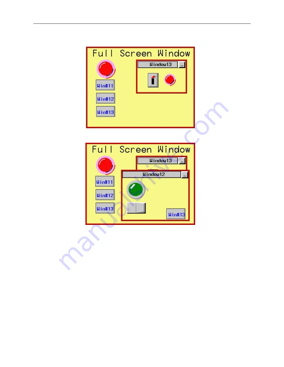
For example, suppose that you have a full screen that calls up Popup Window #13.

If the full screen calls a popup window (with coherence disabled), it displays on the OIT screen over any other
popup windows that might occupy the same area.  In this example, the full screen calls up Popup Window #12.

1010-1001a, Rev 02

88

Sil ver  Se ries  In stal la tion  &  Op er a tion  Man ual

Содержание Silver HMI504T

Страница 1: ...1010 1001A Rev 02...

Страница 2: ...by implication or otherwise under any patent or patent rights of Maple Systems Inc Maple Systems retains the right to revise or change its products and documentation at any time without notice IF SERV...

Страница 3: ...s 36 The EasyASCIIFontMaker 37 EasyBuilder s Default Text Fonts 37 Using the EasyASCIIFontMaker 37 The EasyBuilder Application 38 Managing Projects 39 Printing Projects 41 Editing and Creating Screen...

Страница 4: ...18 Creating XY Plots 220 Chapter 11 Capturing Alarms and Events 223 Using Alarms 223 Monitoring Alarms with the Alarm Scan Object 223 Displaying Alarms using the Alarm Display Object 224 Displaying Al...

Страница 5: ...eries OITs please visit our website About Your Documentation Maple Systems provides many resources to allow you to get the most out of your Silver Series OIT Silver Series Operation Manual shipped wit...

Страница 6: ...7431 0098 Personal Computer2 User Provided Power Cable 6030 0009 24VDC Power Supply 3 User Provided for details refer to Appendix A Specifications PLC User Provided Controller Information Sheet Maple...

Страница 7: ...le Switch Object creates a graphic object on the OIT that when pressed activates a bit in the PLC Graphics Object A graphics object is any text icon or picture that can be displayed on the OIT Graphic...

Страница 8: ...ad of downloading the project to the OIT The Silver Series is powered using 24VDC The viewing level of the OIT display can be adjusted using a contrast switch located on the back of the unit or using...

Страница 9: ...Function Key Creates a touch screen graphics object which displays a window or edits a PLC register Numeric Input Displays a number stored in a PLC register The number can be changed using a numeric k...

Страница 10: ...s that occur in the PLC Alarm Scan Contains the data for detecting alarm conditions System Message Customizes the content of system generated messages PLC Control Configures the OIT to monitor PLC dat...

Страница 11: ...rements per Council Directive 89 336 EEC The European Union created these requirements to ensure conformity among products traded in those countries Specifically the Silver Series OITs meet or exceed...

Страница 12: ...ower supply used for inductive loads or for input circuitry to the programmable logic controller Severe voltage spikes caused by these devices may damage the OIT Control Panel Design Guidelines Pay ca...

Страница 13: ...of the enclosure Corrosion develops over time and prevents good electrical contract For this reason a separate wire braid should be installed from the hinged control panel to the rest of the enclosur...

Страница 14: ...ode attenuation Do not use the power supply used to provide power to the OIT to power switching relays solenoids or other active devices Cable Routing and Noise Immunity Follow these guidelines when r...

Страница 15: ...using an axial ferrite coil Maple p n 2531 0001 with each HMI550 OIT to further reduce the electrical interference that may be conducted on the power lines Thread the positive and negative wires of th...

Страница 16: ...h reliability Most cables are available for next day shipment from Maple Systems Components and instructions necessary to construct your own OIT to PLC communications cables are also available Refer t...

Страница 17: ...and not form a seal with the gasket The area of the panel or mounting surface where the gasket comes into contact must be flat and free of scratches pits and other features that prevent the gasket fro...

Страница 18: ...l cutout when a NEMA 4 seal is required For best results also replace the gasket itself Configuration Wiring The OIT must be configured for a particular protocol before use The EZware 500 software use...

Страница 19: ...n be used to reinitialize the OIT if the OIT malfunctions Only Dip switch 1 and 2 have functionality Dip switch 1 puts the OIT into Touch Calibration mode Dip switch 2 forces the OIT into download mod...

Страница 20: ...1010 1001a Rev 02 16 Silver Series Installation Operation Manual OIT to PC Serial Port Pin Assignments...

Страница 21: ...ements Pentium based 90MHz or higher processor 16 MB of RAM more memory improves performance 10 MB available hard disk space VGA or higher resolution monitor set for 256 color 800x600 pixel mode Micro...

Страница 22: ...tarting EZware 500 Before you can create a sample project you must start the configuration software The EZware 500 software has three main applications EasyBuilder used to create the project downloade...

Страница 23: ...project the project is already included in your EasyBuilder software with the following filenames HMI504T EPJ sample project for the HMI504T HMI520T EPJ sample project for the HMI520T HMI530T EPJ sam...

Страница 24: ...tore up to 1999 predefined windows but screens 0 9 are reserved Therefore the first window screen that is available for configuration is Window 10 By default this is the startup screen when you begin...

Страница 25: ...EasyBuilder you should see the function key that you just created move and or change size This function key is used to display Window 11 4To create a second function key on Window 10 1 We could creat...

Страница 26: ...g box appears 7 Click on the white color box then click OK The color box should reflect the color that you have chosen 8 Click OK 9 Select Window_11 in the Open Window dialog box 10 Click Open The mai...

Страница 27: ...On the main screen of EasyBuilder you should see the scale that you just created move and or change size This scale should be enclosed by the rectangle 4To create a meter display on Window 11 1 From...

Страница 28: ...e and select JOG 4 Enter 1 in the Inc value box 5 Click on the pull down box of JOG Delay and select 0 5 second 6 Enter 100 in the Attribute Upper limit box 7 Click the Shape tab 8 Click Use shape the...

Страница 29: ...k on the second increment key The Set Word Object s Attribute dialog box appears 6 In the General tab section change the Description to Decrement Button 7 Click on the pull down box of the Set Style A...

Страница 30: ...r results 3 If no errors occur click Close The main screen of EasyBuilder reappears If errors have occurred repeat the steps in the Creating a Sample Project section 4Downloading your first project 1...

Страница 31: ...pup window 5 Press the increment and decrement keys on the OIT to see the value in the data register and scale meter change Press the OFF function key to remove the popup window CONGRATULATIONS You ha...

Страница 32: ...1010 1001a Rev 02 28 Silver Series Installation Operation Manual...

Страница 33: ...at is seen when the OIT executes the project file You can use the mouse on your computer to simulate the operation of the touch screen on the OIT Rather than waiting two minutes to test each change yo...

Страница 34: ...it can be done by creating additional windows on the OIT which allow PLC data input 4To use off line simulation mode from EasyBuilder 1 If the project has been modified since the last time it was save...

Страница 35: ...poll communicates the following information The window from which the register or block of registers is called Win000 are background tasks such as alarm scan objects Time it took to get the data Regis...

Страница 36: ...tion in the Direct mode Note the following restrictions Maple Systems standard communication cables will not work in Direct mode The OIT end of the cable must be wired for the PC s serial port To simu...

Страница 37: ...y 24V 0V FG P C 2 3 2 P L C 4 8 5 P L C 2 3 2 A U X 2 4 3 8 2 5 Shielded Power Cable Maple P N 6030 0009 OIT Power Supply Output FG DC Output V Gnd DC Output V 24V Power connector PC Com2 Com1 Printer...

Страница 38: ...500 configuration software 1010 1001a Rev 02 34 Silver Series Installation Operation Manual PC If mouse is using Com 1 use Com2 Maple Systems OIT programming cable P N 7431 0098 RS 485 Com2 Com1 Prin...

Страница 39: ...odify the text fonts that are used in EasyBuilder By the end of this chapter you should be quite familiar with the operation of EasyManager and EasyASCIIFontMaker You will also be able to maneuver aro...

Страница 40: ...ecompiled before they can be modified by the EasyBuilder software To decompile go to the Tools menu and select Decompile Browse for your file and then press the Decompile button This will create a epj...

Страница 41: ...stored in a file called ASCFONT 16 The Type 24 font is used to display the size 24 48 72 and 96 font characters These font characters are stored in a file called ASCFONT 24 Using the EasyASCIIFontMak...

Страница 42: ...Shows how the characters look in various Zoom modes View x3 Shows how the characters look in various Zoom modes View x4 Shows how the characters look in various Zoom modes Toggle In Edit mode using t...

Страница 43: ...Builder will open save close and print files using the standard windows format Opening Editing Projects 4To create a new project 1 On the File Menu click New or click the New icon in the Standard tool...

Страница 44: ...gles A project s display mode may be changed after the initial selection has been made To set Display Mode select Edit System Parameters and select the Hardware tab To change the Display Mode resize t...

Страница 45: ...x appears 2 In the Compress frame box under Source Name select the project epj file that you wish to compress File must have a cmp extension 3 Click Compressing to begin The utility will compress the...

Страница 46: ...g box appears 2 Click Window_12 3 Click Open Window_12 appears in the work area of EasyBuilder Display Options Before we begin describing some of the commands that can be used to edit graphics objects...

Страница 47: ...he Window Treebar To display a window that is not yet open double click on the window number This will automatically open the window and display it 4 To change any settings or close an open window cli...

Страница 48: ...rea covered with grid lines These grid markings can be helpful when trying to align objects that are created on the work area If grid lines are selected you can decide what size each grid is 1 On the...

Страница 49: ...new location However you may find it difficult to select an object without accidentally moving it just a little At times this may be frustrating so you may want to disable the move feature using the...

Страница 50: ...an object that is underneath another object on the screen To use this option you must first select the overlapping object 2 On the Edit Menu click Select Next Object or click on the Select Next Objec...

Страница 51: ...e setting as the distance from the left side of an object to the left side of the next object and the Y Distance setting as the distance from the top of one object to the top of another object The Int...

Страница 52: ...ne of the small black squares The cursor changes to a double arrow icon to indicate that it is in resizing mode 3 Click and drag the mouse to resize the object 4 Objects can also be resized by changin...

Страница 53: ...ale meter in Window_12 is such an example This meter is actually composed of three separate objects a rectangle a scale a meter display These objects are then overlaid to represent the scale Grouping...

Страница 54: ...an arc object that are overlaid on each other in Window_12 of the sample project 4Using the top and bottom layer commands 1 Select one of the layered objects In this example select the layered rectang...

Страница 55: ...d during development The Part Layout setting is global and affects all PLC controlled objects in the application Nudging Objects Nudging is used to fine tune the movement of objects in the work area o...

Страница 56: ...gn For this example select the three rectangle objects of Window_12 2 From the Edit menu click Align then Right or click the appropriate icon from the Manager toolbar 3 From the Edit menu click Undo t...

Страница 57: ...to align For this example select the three rectangle objects of Window_12 2 From the Edit menu click Align then Bottom or click the appropriate icon from the Manager toolbar 3 From the Edit menu click...

Страница 58: ...align For this example select the three rectangle objects of Window_12 2 From the Edit menu click Align then Vert Center or click the appropriate icon from the Manager toolbar Centering is based on th...

Страница 59: ...ngle objects of Window_12 2 From the Edit menu click Make Same Size then Width or click the appropriate icon from the Manager toolbar EasyBuilder always uses the width of the last object that was crea...

Страница 60: ...rectangle finally the right rectangle See what happens when the make same height command is applied to the center and right rectangles 4The make same size command 1 Select the objects you wish to make...

Страница 61: ...the left triangle object of Window_12 2 From the Edit menu click Flip Vertical or click the appropriate icon from the Manager toolbar 3 From the Edit menu click Undo to put the left triangle object b...

Страница 62: ...you wish to lock 2 From the Edit menu click Pinned or click the appropriate icon from the Manager toolbar 3 To unlock the object deselect Pinned from the Edit menu or click the appropriate icon from t...

Страница 63: ...registers to a logical selection for the new PLC protocol however se strongly recommend that you review these changes to assure that they are satisfactory 2 If you haven t already done so select the...

Страница 64: ...d Parameters 3 6 are not used 6 Set the OIT Station No used by some protocols that require the OIT to have a unique network address Consult your Controller Information Sheets for information on the pr...

Страница 65: ...oll Selects the number of pixels that the text on the Alarm bar scrolls to the left on each scroll The speed of the scroll can also be controlled 3 No of Windows Selects the maximum number of pop up w...

Страница 66: ...when called and remains in front re gardless of other subsequent windows displayed Attribute Determines how the common window is drawn Below Base Screen The base window is placed in front of the commo...

Страница 67: ...n a non configured area on the touch screen is touched Inactive area Sets the background color of the touch indicator when an inactive area on the touchscreen is touched An inactive area is an area th...

Страница 68: ...ator Color Sets the color of the alarm indicator Security Settings Configuration The Security tab is used to configure the security features in the OIT The OIT supports three levels of security The se...

Страница 69: ...control box is unchecked Password Level 1 is used to enter the numeric password for access to level 1 the middle security This field is not visible if the security control box is unchecked Password Le...

Страница 70: ...or messages Level 1 is the highest level and generates both error and warning messages regarding part and PLC address size mismatch Level 0 is the default setting The Part Layout setting allows you to...

Страница 71: ...se start address The starting RW address in which Eventlog data is stored When the memory is full new Eventlog data is written to this address overwriting the existing data System Parameter Enables st...

Страница 72: ...nd to the PLC requesting data for each register that is displayed on screen For instance if you have five data fields configured on the OIT to monitor R1 R2 R3 R4 and R5 of a GE PLC then the OIT sends...

Страница 73: ...set to 10 the OIT will send two commands one to get R1 and R10 another to get R40 If the PLC block pack were set to 0 then the OIT would have sent three commands In this case however the three comman...

Страница 74: ...ne PLC Most of the PLCs on the market communicate to OITs using a master slave format The PLC typically behaves as the slave responding to requests from the OIT for data and not initiating any communi...

Страница 75: ...er 2 At the bottom of the menu click System Parameters The Set System Parameters dialog box appears 3 The dialog box has three tabs PLC General and Indicator Select the PLC tab 4 Select Slave from the...

Страница 76: ...a from Master OIT local memory and the PLC No additional communications modules other than possible network infrastructure such as routers hubs and switches are required providing an effective an inex...

Страница 77: ...ory and status of a master OIT If a router is to be used for connecting to a different network then enter the router IP address and configure the router to address the PLC on its network See the illus...

Страница 78: ...have the same Server PLC address 4To configure Master OITs to talk with a PLC over the Ethernet port 1 Click on Edit System Parameters and select the PLC tab 2 Select PLC Type as Modbus RTU TCP IP 3...

Страница 79: ...thernet Slave OIT to the PLC The slave OITs may access data in the PLC in two ways 1 It may write to the local words bits in the master OIT via Ms_LW and Ms_LB registers and those values may be transf...

Страница 80: ...available in the HMI504T PLC RS 232 AUX RS 232 Port Pin Designations Pin assignment of the 9 pin female Sub D PLC RS 232 Port Pin Symbol PLC RS 232 AUX RS 232 1 Aux_TxD Transmitted Data 2 TxD Transmi...

Страница 81: ...arameters to match your PLC 4 Set Data bits Stop bits Baud rate and Parity These must match your PLC settings 5 Set parameters 1 6 which are dependent on the individual driver selected 4 To set Aux ID...

Страница 82: ...m the Aux device by issuing one command for a block of registers instead of a command for each individual register In some cases this speeds the update of information on the display but in other cases...

Страница 83: ...ly moved about the OIT display to allow portions of other windows to come into view Windows can be minimized to an icon on the bottom of the OIT display This feature allows the plant floor operator to...

Страница 84: ...ow menu and select from the list of windows currently open You can also cascade or tile the open windows to see the windows at the same time EasyBuilder requires more resources from your computer ever...

Страница 85: ...The Open Window dialog box reappears 5 If you wish to open the window you just created click on the window and click Open Otherwise click Close to return to the main screen of EasyBuilder Window Setti...

Страница 86: ...lowest available number to the window However you can assign any number within the allowed range In this manner you can group windows together that may share some common traits Assigning a Position T...

Страница 87: ...eight is 100 240 234 for the HMI520T 480 for the HMI530 550 pixels Window Styles There are several options that can be assigned to each window created that affect how it operates with other popup wind...

Страница 88: ...to display popup window 13 If window 13 has the tracking feature enabled then moving window 12 the parent will cause window 13 the child to move as well This is because window 13 was called from an ob...

Страница 89: ...IT screen For instance suppose the OIT display is currently showing a full screen window with several touch screen objects If a popup window is displayed which does not have the monopoly feature enabl...

Страница 90: ...T For example you might construct a dialog box that asks the OIT operator if some step in the control process has been performed The dialog box would have Yes and No function key options which with th...

Страница 91: ...currently displayed on screen The coherence feature causes the popup window to be displayed underneath all other windows currently displayed In other words the coherence feature makes that window sub...

Страница 92: ...If the full screen calls a popup window with coherence disabled it displays on the OIT screen over any other popup windows that might occupy the same area In this example the full screen calls up Pop...

Страница 93: ...ty level to each of the window screens 3 Create a Numeric Input Object that allows you to change the current access level 4To assign Window Security Level passwords 1 From the Edit menu select System...

Страница 94: ...ter no password is required This feature enables someone who has the highest security level to switch the OIT to a lower level without having to memorize all three passwords Assigning Underlay Windows...

Страница 95: ...ferent background color 1 From the Window menu select Open Window The Open Window dialog box appears 2 Click on the window that you wish to change the background color Click Setting The Window Setting...

Страница 96: ...imited only by the total amount of memory available within the OIT How to Display Base Windows Base windows can be displayed on the OIT screen by using a function key to display the window or by using...

Страница 97: ...n the OIT display as determined by the X and Y position in the Window Settings box for that window For more information on using the Function Key object see the chapter on Representing Data with Graph...

Страница 98: ...indow to the next consecutive address after the address specified in this step 4 Select either BIN binary or BCD format 5 Click OK to return to the PLC Control Object dialog box 6 You should see a new...

Страница 99: ...ar to the PLC Control Object the OIT continuously monitors the selected PLC data register It will display any popup window that corresponds to the number placed into the PLC data register by the PLC T...

Страница 100: ...e of the popup window is determined in the Window Settings dialog box This size refers to the area of the Direct Window Object which is analogous to a box in which the popup window is to be placed If...

Страница 101: ...vice Type and Device Address 3 Select BIN or BCD format 4 No of Words is currently set to 1 and cannot be changed This represents a 16 bit PLC data register 5 Click OK to return to the main screen of...

Страница 102: ...PLC address that you have selected The Function Key Object can be made local to one or more windows by placing the object on only those windows It can also be made global meaning the OIT operator can...

Страница 103: ...object more about Set Word and Set Bit objects in a succeeding chapter Creating a moving window The popup windows that you create for display on the OIT can be configured so that the OIT operator can...

Страница 104: ...e 2 From the Parts menu select Function Key The Create Function Key Object dialog box is displayed 3 Click Minimize Window 4 Click the Shape tab Click Use Shape Click on the Shape Library command Sele...

Страница 105: ...Function Key Object dialog box is displayed 2 Click Close Window 3 Configure the rest of the function key and then click OK 4 Place the function key object onto the popup window Placing a close window...

Страница 106: ...4 To Access the common window 1 From the Window menu select Open Window The Open Window dialog box appears 1010 1001a Rev 02 102 Silver Series Installation Operation Manual...

Страница 107: ...popup windows from the common window As with full screen base windows popup windows can be called from the common window In the System Parameters settings you have the option of selecting any popup w...

Страница 108: ...lustration shows how this setting affects the operation of popup windows called from the common window Popup window 21 was called from the common window with the Popup Window Normal setting Window 13...

Страница 109: ...13 Displaying the common window above below the base screen This setting resolves the conflict that can occur if a graphics object on the common window occupies the same space on the OIT display as a...

Страница 110: ...ects such as circles lines rectangles etc Therefore a Set Word object on a base window will cover a Rectangle object on a common window which occupies the same space even with the Above base screen at...

Страница 111: ...ate a Function Key object that is used to change the common window From the Parts menu click Function Key The Create Function Key Object dialog box appears 5 On the General tab click Change Common Win...

Страница 112: ...a window that is always accessible like a common window but not always displayed For example you may want a numeric keypad available for any data entry However a keypad takes precious space on the OI...

Страница 113: ...ction window 1 From the Window menu select Open Window The Open Window dialog box appears 2 Highlight the Fast Selection Window and click Settings The Window Setting dialog box appears 1010 1001a Rev...

Страница 114: ...th 70 and Height 214 The default was selected to create a sidebar that contains function keys to display other windows The example below illustrates how the Fast Selection Window can be used for this...

Страница 115: ...u key for switching screens on the OIT display The following example illustrates how you might create a Fast Selection window for this purpose The example steps you through creating six full screen ba...

Страница 116: ...ibute and place the object into the Fast Selection window Finally the Task Bar must be enabled see the next section for instructions After downloading the project file to the OIT the following initial...

Страница 117: ...Press the Fast Selection key on the Task Bar to activate the Fast Selection window Press one of the Function Keys to switch to another full screen window 1010 1001a Rev 02 Creating Windows 113...

Страница 118: ...70 to at least a minimum of 100 This is because the minimum allowable width size for base windows is 100 2 Create a base window that is the same width and height as the fast selection window you just...

Страница 119: ...e compile and download the project to your OIT Below is an illustration of what the default fast selection window Window 11 alternate fast selection window and Window 10 startup window might look like...

Страница 120: ...been configured to change the fast selection window to Window 11 Window 11 will remain the Fast Selection window until a function key with the Jog FS attribute is used to change the Fast Selection wi...

Страница 121: ...on window that you create Displays information about the activity of your OIT as an option The Task Bar is optional and must be enabled to see it on the OIT screen 4To activate the task bar 1 From the...

Страница 122: ...ed However once the popup window is displayed pressing this key serves no purpose and then it becomes an inactive area 4To activate the touch indicator 1 From the Edit menu select System Parameters Th...

Страница 123: ...4To activate the Alarm indicator 1 From the Edit menu select System Parameters The Set System Parameters dialog box appears 2 Click the General tab to display the General form 3 In the Task Button fra...

Страница 124: ...Selection Window Creating a Message Board You may have an application for an OIT in which the OIT operator must be able to leave messages for someone else to read The message board feature creates a p...

Страница 125: ...option 4 Select Set operation mode from the pull down 5 Click the Attributes button to select the operation mode you want to use 6 Click OK to exit the Create Function Key Object dialog box 7 Place th...

Страница 126: ...he Create Function Key Object dialog box appears 2 Click the General tab to display the General form 3 Click the Message Board option 4 Click the Set operation mode pull down box and select Clear boar...

Страница 127: ...rd we recommend that you use some dull pointed device such as a retractable pen that won t mar or leave a permanent mark on the OIT s touch screen Then practice your penmanship 1010 1001a Rev 01 Creat...

Страница 128: ...1010 1001a Rev 01 124 Silver Series Installation Operation Manual...

Страница 129: ...sen 4 Click on the line thickness that you want to use 5 Move the mouse cursor over to the work area of EasyBuilder onto the window that you are currently editing The mouse cursor has changed from an...

Страница 130: ...olor for the Interior box Click Pattern Style to display the Pattern Style dialog box Select the upper left most pattern for a solid color If you want to use a pattern for the filled section of the el...

Страница 131: ...box to go back to the Attributes dialog box 5 Click on the line thickness that you want to use 6 Move the mouse cursor over to the work area of EasyBuilder onto the window that you are currently edit...

Страница 132: ...e four shades available in the HMI520M and HMI550M The text can be left center or right justified in the text box 4To create a text box 1 From the Draw menu click Text Or click the Text icon in the Dr...

Страница 133: ...nce between shapes and bitmaps is how they are composed and stored Shapes are vector based graphics which are stored in files that contain dimensional information about the shape Shapes are actually c...

Страница 134: ...Objects Information on creating new shapes and bitmaps and storing them in libraries will be covered in a later section of this chapter Using a Predefined Shape You can select from many shapes that ar...

Страница 135: ...with an outline of the shape object in the upper left corner of the work area 7 Move the shape to the location desired and click The shape appears with small square boxes around the perimeter of the s...

Страница 136: ...use a bitmap 1 From the Draw menu click Bitmap Or click the Bitmap icon in the Draw toolbar The Create Bitmap Object dialog box appears 1010 1001a Rev 02 132 Silver Series Installation Operation Manu...

Страница 137: ...phics Libraries Graphics Libraries are files that come with EasyBuilder which contain graphics shapes and bitmaps Over 500 predefined shapes and bitmaps are included with EasyBuilder In addition you c...

Страница 138: ...ibraries have at least two states Using Shape Libraries EasyBuilder includes fourteen shape libraries balloons slb contains dialog boxes captions slb contains various rectangle shapes button1 slb swit...

Страница 139: ...ed library displayed If the project has ten libraries open you may want to close a library so that another one may be opened 4To close or unattach an open shape library 1 With the Shape Library dialog...

Страница 140: ...ow to use the drawing tools consult the first part of this chapter The shapes that you create can be permanently stored into the shape libraries for access by any project 4 To add a new shape to a lib...

Страница 141: ...rs 4 Click the Shape library box and select the library you wish to store the shape in for this example eggs 5 Click the Shape No pull down box to select the location 0 to store the shape Note that th...

Страница 142: ...EasyBuilder 9 From the File menu click Save to save the shape to the library Important you must save before attempting to store the next shape 10 Highlight the other shape by clicking the mouse and d...

Страница 143: ...stems may overwrite existing libraries during installation This will delete any new shapes that you have entered Therefore we recommend that you create new libraries to store these shapes or make back...

Страница 144: ...rary If you find that some of the shapes included in the libraries are not useful you have the option of deleting them so that they may be replaced by another shape 4 To delete a shape from a library...

Страница 145: ...ton1 3 Click on the shape that you want to place on the work area For this example select item 12 4 Click Place The main screen of EasyBuilder reappears with the shape in the upper left corner of the...

Страница 146: ...he Bitmap Library provides several options which are discussed in the following sections Accessing and Creating Bitmap Libraries You can open close or even create new bitmap libraries easily using the...

Страница 147: ...not stored into the Library subdirectory of EasyBuilder until the project file has been saved Creating and exporting bitmaps Although EasyBuilder does not provide the ability to create bitmaps the sof...

Страница 148: ...he Get Bitmap Graphics dialog box appears 9 Click Browse to search for the bitmap The Open dialog box appears Select the bitmap file and click Open 1010 1001a Rev 02 144 Silver Series Installation Ope...

Страница 149: ...very useful when you want to overlap several bitmaps for example when configuring a bar graph To use the transparent feature click on the bitmap picture in the Get Bitmap Graphics dialog box on the co...

Страница 150: ...tly save the bitmap to the library When adding new bitmaps to existing libraries that come with the EZware 500 software remember that any future upgrade that you receive from Maple Systems may overwri...

Страница 151: ...rk area of EasyBuilder can be grouped together and stored into a group library Graphics objects can be passive or active The groups that you create can be permanently stored into the group libraries f...

Страница 152: ...alog box displayed click the pull down box of Library Name and choose from one of the open libraries of groups 2 Select which library you would like to close then click Unattach Lib A dialog box appea...

Страница 153: ...ee small black squares around the perimeter of the group For this example the scale meter shown at the beginning of this section is highlighted 2 From the Library menu click Group then Save to library...

Страница 154: ...be replaced by another group 4 To delete a group from a library 1 From the Library menu click Group then Call up library 2 Select the library that the group is located in 3 Click on the group that you...

Страница 155: ...group objects with EasyBuilder This chapter also provided some examples on how to use the drawing tools The next several chapters describe the many parts or active graphics objects that can be placed...

Страница 156: ...1010 1001a Rev 02 152 Silver Series Installation Operation Manual...

Страница 157: ...ing through Label selection from the Label Library The Label text may also be represented in up to 4 languages each selectable for display Creating and Using the Tag Library The Tag Library is a datab...

Страница 158: ...ved the file can be loaded into another project 4To save the tag library 1 Click on Save Tag File The Open dialog box appears 2 Enter the name of the file where you wish to save the data 3 Click Open...

Страница 159: ...Device Type list will be filled with a list of available tags Objects addressable as Register type objects will display Tags configured as Word Objects addressable as Bit type objects will display Ta...

Страница 160: ...l by opening the Label Library as detailed above and Clicking the Add button to display the Label dialog 3 Enter the Title Name for the label and how many states the new label requires For example a l...

Страница 161: ...ting select the state requiring text labeling Enter the text in the Language boxes as above There is no inter language conversion or translation capability Entries must be made using the correct wordi...

Страница 162: ...eful if you need to make several changes to the database When creating a new project it is easier and faster to create tags as csv files 4To export the label library 1 Click Export CSV File The Open d...

Страница 163: ...bjects can be viewed displaying the various text labeling in each of the states detailed in each of the languages utilized To view on EZBuilder s Standard Toolbar select the state and language for obj...

Страница 164: ...brary In LW9130 a Value of 0 enables Language 0 as configured in the Label Library a Value of 1 enables Language 1 a Value of 2 enables Language 2 and a Value of 3 enables Language 3 2 The appropriate...

Страница 165: ...writing a 1 to LW9130 will enable text display in French Continue for all Languages configured in the Label Library 1010 1001a Rev 02 Creating and Using Tags and Databases 161...

Страница 166: ...1010 1001a Rev 02 162 Silver Series Installation Operation Manual...

Страница 167: ...IT with these addresses the slave will read write to the corresponding LW address in the master OIT This can be used to exchange information between slave and master OITs Ms_LB Master Slave Local Bit...

Страница 168: ...ssage Board Pen width 2 R W Set this bit to select Pen Width 2 pixels for the Message Board feature 9032 Message Board Pen width 3 R W Set this bit to select Pen Width 3 pixels for the Message Board f...

Страница 169: ...meric Input Object or ASCII Input Object located on the right side of the keypad The OIT clears this bit when user presses the Enter or ESC keys 9065 Keypad Control AI or NI located on right side of k...

Страница 170: ...9008 Message Board Pen Color RdOnly This value represents the current pen color 0 255 of the Message Board 9009 Reserved for future use 9010 Local second bcd 0 59 R W When the local Word Option is sel...

Страница 171: ...t is being released If LW9044 0 the coil assigned to the momentary key is cleared when the operator releases the key even if a popup window is now overlaid on top of the key If LW9044 1 in this mode n...

Страница 172: ...splay on OIT 9094 Project Compiled Date Day RdOnly This register contains the day of month date when the project was last compiled Use the Numeric Data Object Decimal Display to display on OIT 9095 90...

Страница 173: ...1 RS485 60041 Baud Rate 0 9600 1 192002 38400 3 576004 115200 60042 Data Bits 0 7 1 8 60043 Parity 0 none 1 even 2 odd 60044 Stop Bits 0 1 1 2 60045 HMI Station Address 0 255 60046 PLC Station Addres...

Страница 174: ...eter is set to Yes then set a bit of LB 9044 to ON will restore these system parameters from these recipe word memory Representing PLC Coil Registers PLC coils or binary registers and internal coils o...

Страница 175: ...Attribute frame select how you want the Bit Lamp object to operate Function Option Description Normal Displays State 0 object when coil is clear displays State 1 object when coil is set Blinking on St...

Страница 176: ...Shape form 6 Select either a shape or bitmap to represent the Bit Lamp object If you need more information on how to do this consult Chapter 6 Creating Graphics Objects 1010 1001a Rev 02 172 Silver S...

Страница 177: ...of one label when it is moved after the Bit Lamp object is placed onto the window 14 Click OK The Create Bit Lamp Object form closes and the main screen of EasyBuilder appears with the cursor tied to...

Страница 178: ...when the window that the part is located in is opened Set OFF at window open Automatically clears a PLC coil when the window that the part is located in is opened Periodical toggle Automatically sets...

Страница 179: ...ay prefer to place the part on the window without a shape or bitmap tied to it 6 Refer to the Bit Lamp Object section for information on using the Label tab 7 Click OK The Create Set Bit Object form c...

Страница 180: ...PLC coil when pressed Toggle Alternates between setting and clearing a PLC coil Momentary Sets a PLC coil when pressed clears a PLC coil when released 6 Refer to the Bit Lamp Object section for infor...

Страница 181: ...in the previous section With these parts however you can represent data from 16 bit 32 bit or even 64 bit data registers The Word Lamp Object The Word Lamp Object is used to represent the value of a P...

Страница 182: ...from 1 to 32 states If the actual value in the PLC register is out of range for the number of states specified then no shape or bitmap is displayed 5 Click the Shape tab to display the Shape form 6 Se...

Страница 183: ...t of one label when it is moved after the Word Lamp object is placed onto the window 14 Click OK The Create Word Lamp Object form closes and the main screen of EasyBuilder appears with the cursor tied...

Страница 184: ...ant used Range 32768 to 65535 Add value JOG Increases the value in a 16 bit PLC register by a step value each time it is pressed Inc value Amount of the step value Range 1 to 32767 Upper limit The upp...

Страница 185: ...at which the automatic decrementing occurs Range 0 1 to 25 5 seconds in 0 1 second increments Periodical bounce Automatically increases the value in a 16 bit PLC register by a step value at a predefi...

Страница 186: ...pe or bitmap tied to it 6 Refer to the Bit Lamp Object section for information on using the Label tab 7 Click OK The Create Set Word Object form closes and the main screen of EasyBuilder appears with...

Страница 187: ...escription JOG Increments the PLC register by 1 each time the key is pressed When the highest state is reached the key resets to State 0 No of states Range 1 to 32 JOG Decrements the PLC register by 1...

Страница 188: ...register can be a 16 bit 32 bit or a 64 bit word 4To create a Numeric Data Object 1 From the Parts menu click Numeric Data Or click the Numeric Data icon in the Part1 toolbar The Create Numeric Data O...

Страница 189: ...nary 16 bit format 00 to 11 32 bits 2 binary 32 bit format Mask 1 2 masks the value with asterisks Single Float 999999999 9999999999 to 9999999999 9999999999 2 EEE 754 format single precision Double F...

Страница 190: ...alue that is in the PLC data register Engineering low 2147483648 to 2147483647 This is the lowest data value that you would like displayed on the OIT Engineering high 2147483648 to 2147483647 This is...

Страница 191: ...bit or a 64 bit word By using the keypad the OIT operator can enter a new value 4To create a Numeric Input Extend Object 1 From the Parts menu click Numeric Input Extend Or click the Numeric Input Ex...

Страница 192: ...32 bit format Mask 1 2 masks the value with asterisks Single Float 999999999 9999999999 to 9999999999 9999999999 2 IEEE 754 format single precision Double Float 999999999 9999999999 to 9999999999 9999...

Страница 193: ...low 0 to 2147483647d This is a decimal number which the OIT converts to hexadecimal for establishing the lowest value that the OIT operator is allowed to enter For example if you want the minimum hex...

Страница 194: ...647 This is the highest data value allowed when the OIT operator enters a number 9 Click the Shape tab to configure a shape or bitmap that is displayed behind the number 10 Click the Font tab to displ...

Страница 195: ...splay a maximum of 32 characters Each 16 bit register stores two ASCII characters The first ASCII character is stored in the eight least significant bits of the register The 16 bit register that you s...

Страница 196: ...d onto the window you can modify the attributes by double clicking on the part to display the ASCII Data Object s Attribute dialog box The ASCII Input Extend Object The ASCII Input Extend Object is us...

Страница 197: ...OIT internal memory address that is used to trigger write access to the register If the coil is set then write access is enabled If the coil is clear then write access is disabled Note If you want the...

Страница 198: ...en by dragging the text to it s new position The Moving Shape Object The Moving Shape Object performs three functions depending upon the values in three consecutive PLC registers Similar to the Word L...

Страница 199: ...number of registers read depends upon the Style used 4 In the Attribute frame select how you want the Moving Shape object to operate Style Option Description X axis only Reads two 16 bit registers Re...

Страница 200: ...er Range 32767 to 32766 Input high This is the highest raw data value that is in the PLC data register Range 32766 to 32767 Scaling low This is the low scaled value Scaling high This is the high scale...

Страница 201: ...window 8 Once the part is placed onto the window you can adjust the location of the label inside the part by clicking once on the label This will highlight the entire object Click on the label again...

Страница 202: ...Builder Use the cursor to set the path that the Animation object is to take At each location along the path click the mouse to place another position marker A maximum of 255 position markers may be pl...

Страница 203: ...he starting PLC coil or OIT internal memory address that the part reads from You can select BIN binary or BCD format The No of words is set to 2 and cannot be changed 6 In the No of states box select...

Страница 204: ...points pull down box to select the point you wish to change then edit the X and Y positions 14 Click OK The Animation Object s Attribute form closes and the main screen of EasyBuilder appears with th...

Страница 205: ...ll as control keys i e Delete Enter Clear etc 4 To create a Function Key Object 1 From the Parts menu click Function Key Or click the Function Key icon in the Part1 toolbar The Create Function Key Obj...

Страница 206: ...I checkbox Select this when you want to configure the Function Key to enter an alphanumeric character When this checkbox is selected the Character box is activated Use this box to enter the ASCII char...

Страница 207: ...Click OK The Create Function Key Object form closes and the main screen of EasyBuilder appears with the cursor tied to a rectangular outline of the part you just created at the upper left corner of th...

Страница 208: ...roject file with the initial screen configured as the startup screen Note this is the default setting Display the initial screen in the work area of EasyBuilder 2 From the Library menu click Group and...

Страница 209: ...meric Input Register Read Address Device type LW Device address 0 BCD or BIN BIN No of words 1 Trigger address Device type LB Device address 9000 Numeric Display Format Decimal Type Raw data display N...

Страница 210: ...9 Create two text boxes one to identify the Numeric Input register and one to label the ASCII Input register 4Editing data registers using a keypad 1 Save and compile the new project then test the ope...

Страница 211: ...e keypad enter the character string HELLO THERE As you enter the characters each one should appear in the ASCII Input Object box Press the Enter key to send the characters to the OIT internal data reg...

Страница 212: ...000 3 Select the Numeric tab 4 In the Display section select the Decimal option button 5 Click OK 6 Use the mouse cursor to place the Numeric Input register in the center of the screen of Window 10 10...

Страница 213: ...Set Bit Object dialog box 8 Enter the following settings In the Write Address section Device Type LB Device Address 100 Attribute Style ON 9 Place the Numeric Input Object and the Set Bit Object on to...

Страница 214: ...om the menu listings This displays the Open Window dialog box 2 Highlight Common Window and click Open 3 This window has already been configured to display a Direct Window Object shown as a 1010 1001a...

Страница 215: ...listings 2 File name Name the project 3 Click Save 4 Select Tools Compile to compile the project 5 Click COMPILE 6 After the computer has compiled the project click CLOSE 7 Select Tools Offline Simul...

Страница 216: ...1010 1001a Rev 01 212 Silver Series Installation Operation Manual...

Страница 217: ...LC register as a bar graph You can configure the bar graph to move up down right or left The bar graph can be configured with any base number that represents 0 level and any span range You can create...

Страница 218: ...the Shape form 6 A shape or bitmap is not necessary if you plan to display the bar graph as a rectangular object If you do select a shape the bar graph will only show in areas of the shape in which no...

Страница 219: ...arm or out of range condition 10 In the Value frame box select the following Function Range Description Low alarm limit 32768 to 32766 During operation if the PLC register monitored by the bar graph g...

Страница 220: ...reating Display Meters The Display Meter Object is used to represent the data in a 16 bit PLC register as a scaled meter You can configure the Display Meter in four styles Up Half Full Up Full Bottom...

Страница 221: ...lay meter that ranges from 0 to 180 starting at the 9 o clock position Full Up Select for a display meter that ranges from 0 to 360 starting at the 12 o clock position Full Bottom Select for a display...

Страница 222: ...nge Description Page Type Single page or Multiple pages Select Single page or Multiple pages Multiple pages configure the trend display as a window to the trend graph in which different segments can b...

Страница 223: ...old function If the coil is set then the hold function is activated Device address PLC or OIT internal memory address 3 Click the Trend Display tab to display the Trend Display form 4 Use the Descript...

Страница 224: ...the XY Plot icon in the Part2 toolbar The Create XY Plot Object dialog box appears 2 In the General frame select the following attributes Function Attribute Range Description Page Type Single page or...

Страница 225: ...BIN or BCD Select binary BIN or BCD format Hold control Device type If Multiple pages is selected this coil register is used to enable the hold function If the coil is set then the hold function is ac...

Страница 226: ...g box The main screen of EasyBuilder appears with the cursor tied to a rectangular outline of the part you just created at the upper left corner of the screen Move the part to the desired location You...

Страница 227: ...lling line like a marquee You can also use the Alarm Indicator on the Task Bar to determine if any alarms are active For more information on using the Alarm Indicator refer to the section Using the Ta...

Страница 228: ...arm Scan Object dialog box reappears with the new entry listed You can edit the attributes of an existing alarm by clicking on the Setting button Any entries can be deleted by clicking on the Delete b...

Страница 229: ...lects how many alarms to display in the scrollable window The number of lines refers to lines that are Size 16 font If the alarm text string is Size 24 font then two lines are required for every alarm...

Страница 230: ...these onto a startup screen of EasyBuilder Create a Text Object with the string Alarm Display Finally create two Set Word Objects with the Add value JOG attribute and Sub value JOG attribute that incr...

Страница 231: ...arm Display object directly underneath the Alarm Display text string and to the right of the two Set Word objects Save and compile the project then simulate off line The startup screen should appear w...

Страница 232: ...termine what part of the alarm list to show with the scrollable window Use the Up Arrow key to return to the top of the list Using the scrollable window feature on the Alarm Display object allows the...

Страница 233: ...ose the Create Alarm Bar Object dialog box The main screen of EasyBuilder appears with the cursor tied to a rectangular outline of the part you just created at the upper left corner of the screen Move...

Страница 234: ...ect The Event Log Object continuously monitors PLC coils and registers to determine if an event has occurred Once an event has triggered the Event Log Object directs a string of characters associated...

Страница 235: ...auses the text in the Contents box to be printed when the event is triggered or returns to normal Category Not used Reserved for later use 6 In the Text frame enter a text string in the Content text b...

Страница 236: ...he popup window can than be used to display further instructions to the OIT operator or to perform some operation 4 To create an Event Display Object 1 From the Parts menu click Event Display Or click...

Страница 237: ...een each event text string displayed In other words this sets the spacing between the lines of the scrollable window Acknowledge style Click or Double click This setting determines what the OIT operat...

Страница 238: ...ing Events for an Alarm History Events are a complicated feature to understand and it may be a little unclear as to how events can be used So let s go through an application example in which we will u...

Страница 239: ...ting General Write Address LW0 BIN Attribute Style Sub value JOG Attribute Dec Value 1 Attribute Bottom Limit 0 Shape Library button4 Item 28 Label Use Label not checked Profile Width 41 Height 20 3 C...

Страница 240: ...og box appears 2 Enter the following parameters for each event Attribute Setting Address type Bit Read Address LB0 to LB4 Event trig On Text Water Level Low LB0 Fuel Level Low LB1 Coolant Level Low LB...

Страница 241: ...length 31 Text Space 0 Acknowledge Style Click Color Acknowledge Any color Color Return to Normal Any color Color Select box Any color Format Sequence No 3 Click OK Place object directly under the Al...

Страница 242: ...m on the list will remain on the list permanently The alarm message will remain on the list even after the alarm condition goes back to normal The sequence number is handy since it shows the total num...

Страница 243: ...te you may need to transfer large blocks of data from PLC OIT registers to other PLC OIT registers The Data Transfer Object is used to copy data from one or more PLC registers or HMI internal memory t...

Страница 244: ...inuous data transfer Range is 0 to 25 5 seconds in 0 1 second increments Note that selecting a smaller period will decrease the amount of OIT processing time that can be allocated to other tasks 8 Cli...

Страница 245: ...r downloaded to The No of words box is used to specify the total number of 16 bit registers used The range is 1 to 32767 The Device Address you specify for the PLC register is also the starting regist...

Страница 246: ...a shape or bitmap to represent the Recipe Transfer object If you need more information on how to do this refer to Chapter 6 Creating Graphics Objects 7 Click the Label tab to display the Label form 10...

Страница 247: ...OIT s built in Parts to store data in the RW RB devices and then transferring that data to the selected PLC registers Recipe Devices There are 4 types of Recipe devices Recipe Word RW Indexed address...

Страница 248: ...4 For an example of how to create recipes please consult the EZware 500 online Help file 1010 1001a Rev 02 244 Silver Series Installation Operation Manual...

Страница 249: ...reate a new worksheet to program a new macro The programmer first gives the macro a name in the top right corner Then programming can be added After the code is finished it needs compiled If the code...

Страница 250: ...ed where the Type of control was selected first to be Execute macro program Then the device type showed what bit types were available A LB was selected and the address 1 was entered Finally the macro...

Страница 251: ...1010 1001a Rev 02 Macros 247 Set Bit Objects Attributes Dialog Project Example of Add 2...

Страница 252: ...is allotted if the Fast Selection task bar is enabled and the there are other background task objects that also use memory in this area such as Trends XY Plots Data Transfers Alarms Events PLC Control...

Страница 253: ...5 6 7 8 9 10 char LetterArray 6 MYWORD The initial values are written within the brackets and are divided by comma These values are assigned in order from left to right starting from array index 0 Con...

Страница 254: ...precedence Priority of the same kind of operator From left to right from top to bottom Arithmetic operator Bitwise Shift operators From left to right within the expression Comparison operator From le...

Страница 255: ...y of 10 would contain 10 elements of the declared type The first register in an array always begins with the 0th element and the last register is the declared number of elements minus 1 The format is...

Страница 256: ...ess 0 To 29999 SetData Address LW_Binplc 9000 1 LW 9000 incr through memory SetData Initial RWI_Binplc 30000 1 RWI 0 indirect address is Upper Next Address SetData Done LB_Binplc 1 1 Turn off the bit...

Страница 257: ...2 This routine reads a 32 bit holding register short Data 2 grab a 32 bit register 2 16 bit value from a PLC register address 4x 1 GetData Data 0 4x_Binplc 1 2 Statements Conditions Expressions An exp...

Страница 258: ...e program branch will execute the Case Else statement s The ending statement End Select is written as two words Format Examples Select Case TestExpression Case statements n Case Else else statements E...

Страница 259: ...ment It quits the current iteration of a loop and starts the next one return Returns to the function or module that called the current function Format Examples While Condition Statements Wend For n 10...

Страница 260: ...ess the PlcCom button This way all variables will be available in a drop down menu list within the PlcCom dialogHIDD_MACROPLCCOM GetData Function This function reads data from a register location in t...

Страница 261: ...short s Compiler Errors Error Codes When there are compile errors the error description can be referenced by the compiler error message number Error message format Macro_name Error_message_number Erro...

Страница 262: ...Missing Next statement The format of For statement is For variable initial value To end value Step Next variable Any format other than this format will cause compile error 22 While statement error mi...

Страница 263: ...r of GetData SetData should be legal PLC address 39 Should be integer character or constant The format of array is Declaration array_name constant constant is the size of the array Usage array_name in...

Страница 264: ...End Macro_Command 1010 1001a Rev 02 260 Silver Series Installation Operation Manual...

Страница 265: ...ed printer If None is selected no printing will occur 4 If each printed Event is to have a unique serial number printed with it check the Print Sequence Number checkbox 5 If each printed Event is to h...

Страница 266: ...ow s Text Meter Trend Bitmap and Shape objects All shapes and bitmaps on the Window are printed whether they are part of another object Bit Lamp Function Key etc or stand alone Shape and Bitmap object...

Страница 267: ...directed by the PLC 4Using the PLC Control Object to print a report 1 From the Parts menu select PLC Control The PLC Control Object dialog box appears 2 Click Add The PLC Control Object s Attribute d...

Страница 268: ...1010 1001a Rev 01 264 Silver Series Installation Operation Manual...

Страница 269: ...s compressing 148 Bitmaps definition of 131 Bitmaps exporting 149 Blinking feature 173 C Cable Routing and Noise Immunity 10 CE Compliance 7 change language 47 change state 47 Circle tool using 128 Cl...

Страница 270: ...94 G General Settings 63 Graphics Object 3 grid color 46 Grid function 46 grid size 46 Group Libraries definition 149 Group Libraries deleting a group member 152 Grouping objects 51 H Hard Copy 264 Ha...

Страница 271: ...reparation 14 Password Protection 64 PLC block pack feature 70 PLC Control Object 95 PLC displaying windows 95 Polygon tool using 129 Popup Window creating 24 Popup windows displaying 95 Port wiring 1...

Страница 272: ...Box Object using 130 Text fonts 39 Toggle Switch Object using 177 Touch Indicator 65 Touchscreen calibration of 16 Tracking feature 85 Transparent feature bitmaps 147 Trend Display Object using 220 22...

Отзывы: