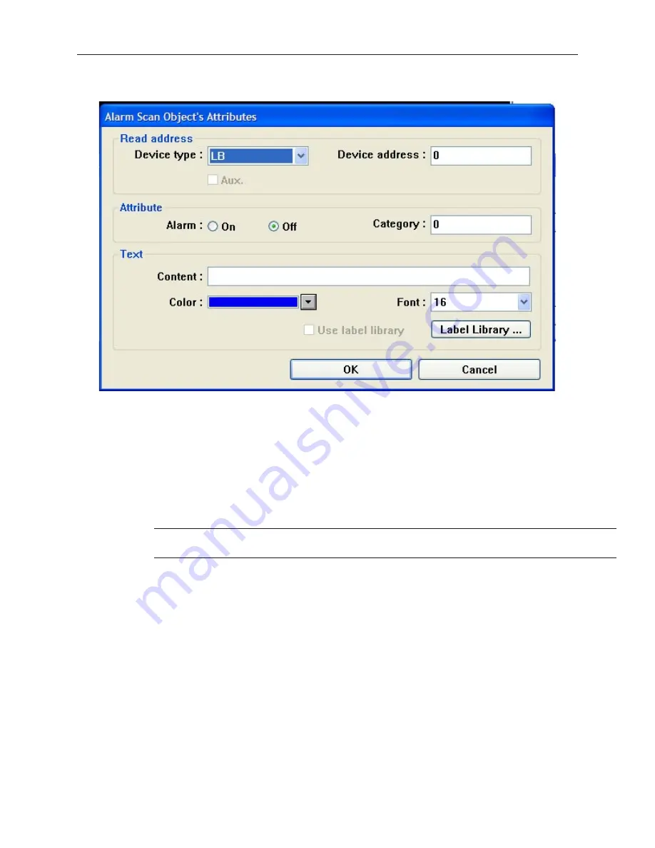
2.
Click the
Add...
button. The Alarm Scan Object’s Attributes dialog box appears.
3.
In the
Read address
frame, select the PLC coil to monitor the alarm condition.
4.
In the
Attribute
frame, for the
Alarm:
setting click
On
or
Off
. Use the On setting to activate
the alarm condition when the PLC coil is set. Use the Off setting to activate the alarm
condition when the PLC coil is clear. The
Category:
setting is reserved for later use.
5.
In the
Text
frame, enter a text string in the
Condition:
text box that is to be displayed when
an alarm condition occurs.
6.
Select the color of the text string in the
Color:
box.
7.
Select the font size of the text string in the
Font:
box. Sizes 16 and 24 are available.
8.
Check the
Use label library
box if you would like to use the database of text labels. Click
the
Label Library...
box to create a new label, if necessary.
4
For more information about how to use the Label Library, consult Chapter 7,
Creating
and Using Databases and Languages.
9.
Click
OK
to close the Alarm Scan Object’s Attributes dialog box. The Alarm Scan Object
dialog box reappears with the new entry listed. You can edit the attributes of an existing
alarm by clicking on the
Setting...
button. Any entries can be deleted by clicking on the
Delete
button.
10. Click
Close
to close the Alarm Scan Object dialog box. The Alarm Scan Object is active no
matter what windows are currently displayed on the OIT screen. Therefore, you do not have
to place the object onto a window screen.
Dis play ing Alarms us ing the Alarm Dis play Ob ject
Though the Alarm Scan Object continuously monitors the PLC for alarms, it cannot display the alarms without the
Alarm Display Object or the Alarm Bar Object. The Alarm Display Object takes the alarm strings sent to it from the
Alarm Scan Object and displays them on a window screen as a list. The list contains all of the active alarms
occurring with the most recently activated alarm at the top of the list. You do not have to display the entire list of
alarms on a window screen. You can limit the viewable alarms to a ‘scrollable window’ that displays a given
number of lines. You can then create a register that allows you to scroll through the list of alarms using the
scrollable window.
1010-1001a, Rev 02
224
Sil ver Se ries In stal la tion & Op er a tion Man ual
Содержание Silver HMI504T
Страница 1: ...1010 1001A Rev 02...
Страница 20: ...1010 1001a Rev 02 16 Silver Series Installation Operation Manual OIT to PC Serial Port Pin Assignments...
Страница 32: ...1010 1001a Rev 02 28 Silver Series Installation Operation Manual...
Страница 128: ...1010 1001a Rev 01 124 Silver Series Installation Operation Manual...
Страница 156: ...1010 1001a Rev 02 152 Silver Series Installation Operation Manual...
Страница 166: ...1010 1001a Rev 02 162 Silver Series Installation Operation Manual...
Страница 216: ...1010 1001a Rev 01 212 Silver Series Installation Operation Manual...
Страница 251: ...1010 1001a Rev 02 Macros 247 Set Bit Objects Attributes Dialog Project Example of Add 2...
Страница 264: ...End Macro_Command 1010 1001a Rev 02 260 Silver Series Installation Operation Manual...
Страница 268: ...1010 1001a Rev 01 264 Silver Series Installation Operation Manual...


