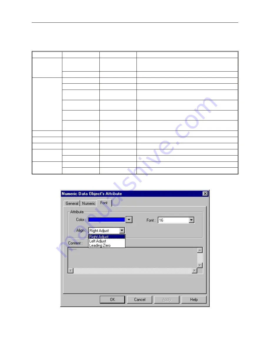
7.
In the
Numeric
attribute box, select how you want the data to be represented. The
Input
low:
and
Input high:
boxes don’t apply unless Decimal format with Do conversion is
selected. The options are:
Format
Options
Range
Description
Decimal (with
Raw data
display)
No. above Dec.:
1-10
specifies number of digits to display (for example, 2 digits
displays -9 to 99); any number that cannot be displayed with
the specified number of digits is represented with asterisks.
No. below Dec.:
0-10
specifies number of digits to the right of the decimal point.
Decimal (with
Do conversion)
No. above Dec.:
1-10
specifies number of digits to the left of the decimal point.
No. below Dec.:
0-10
specifies number of digits to the right of the decimal point.
Input low:
-2147483648 to
+2147483647
This is the lowest raw data value that is in the PLC data
register
Input high:
-2147483648 to
+2147483647
This is the highest raw data value that is in the PLC data
register
Engineering low:
-2147483648 to
+2147483647
This is the lowest data value that you would like displayed on
the OIT.
Engineering high:
-2147483648 to
+2147483647
This is the highest data value that you would like displayed
on the OIT.
Hex
No. above Dec.:
Not Apply (NA)
4 digits are used for 16 bit; 8 digits for 32 bit.
Binary
No. above Dec.:
NA
16 digits are used for 16 bit; 32 digits for 32 bit.
Mask
No. above Dec.:
1-10
the number of asterisks to display
Single Float
No. above Dec.:
1-10
specifies number of digits to the left of the decimal point.
No. below Dec.:
0-10
specifies number of digits to the right of the decimal point.
Double Float
No. above Dec.:
1-10
specifies number of digits to the left of the decimal point.
No. below Dec.:
0-10
specifies number of digits to the right of the decimal point.
8.
Click the
Font
tab to display the Font form.
9.
Enter the color that you want for the digits displayed in the
Color:
box
10. Enter how you want the digits to be positioned in the
Align:
box. The choices are:
1010-1001a, Rev 02
186
Sil ver Se ries In stal la tion & Op er a tion Man ual
Содержание Silver HMI504T
Страница 1: ...1010 1001A Rev 02...
Страница 20: ...1010 1001a Rev 02 16 Silver Series Installation Operation Manual OIT to PC Serial Port Pin Assignments...
Страница 32: ...1010 1001a Rev 02 28 Silver Series Installation Operation Manual...
Страница 128: ...1010 1001a Rev 01 124 Silver Series Installation Operation Manual...
Страница 156: ...1010 1001a Rev 02 152 Silver Series Installation Operation Manual...
Страница 166: ...1010 1001a Rev 02 162 Silver Series Installation Operation Manual...
Страница 216: ...1010 1001a Rev 01 212 Silver Series Installation Operation Manual...
Страница 251: ...1010 1001a Rev 02 Macros 247 Set Bit Objects Attributes Dialog Project Example of Add 2...
Страница 264: ...End Macro_Command 1010 1001a Rev 02 260 Silver Series Installation Operation Manual...
Страница 268: ...1010 1001a Rev 01 264 Silver Series Installation Operation Manual...


