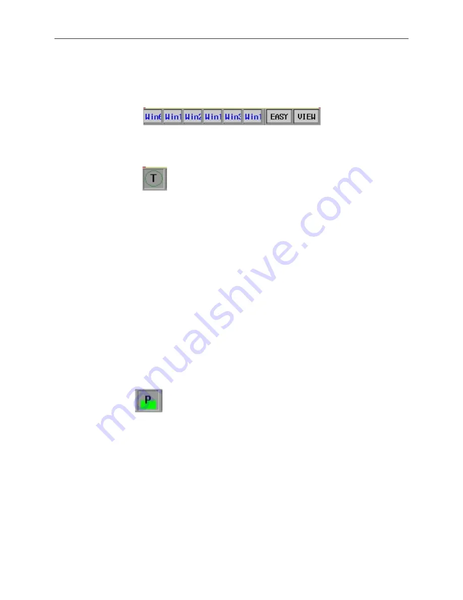
Using the Win dow Bar
The window bar is where the minimized popup window icons reside. You can display a maximum of six popup
windows at one time and every time a popup window is displayed on the OIT screen, an icon representing that
window is displayed on the window bar of the task bar.
The window bar can be displayed or removed by pressing the Window Bar Key labeled
Easy
. Besides containing
the popup window icons, the Window Bar also contains three optional indicators: the
Touch
,
CPU
, and
Alarm
indicators
The Touch In di ca tor
This optional feature provides you with additional feedback when pressing the touch screen of the OIT. One of
three colors is displayed in the circle, depending upon what area of the touch screen is touched. The three areas are:
·
Non-configured area
– Any area on the touch screen that does not contain an active touch screen object.
·
Active area –
Any area that contains an active touch screen object which, when pressed, executes some
action.
·
Inactive area
– Any area that contains an active touch screen object but the active object is not able to
execute its intended function. For example, a Function Key with the Popup Window option is defined as an
active area when first pressed since it causes the popup window to be displayed. However, once the popup
window is displayed, pressing this key serves no purpose and then it becomes an inactive area.
4
To activate the touch indicator
1.
From the
Edit
menu, select
System
Parameters
. The
System Parameter Setting
dialog box
appears.
2.
Click the
General
tab to display the General form.
3.
In the
Task Button
frame, click
Enable
in the
Attribute
box.
4.
Click the
Indicator
tab to display the Indicator form.
5.
In the
Touch Indicator
frame, click
Enable
in the
Attribute
box.
6.
Select which colors you would like to use for the
Non-Configured Area
, the
Inactive Area
,
the
Active Area
, and the
Frame
box.
7.
Click
OK
to exit
the System Parameters
dialog box.
The CPU In di ca tor
This optional feature reflects the status of the OIT’s microprocessor. As the color indicator grows, the
microprocessor of the OIT is processing more data. The CPU indicator could be used as a rough indicator of how
much activity is occurring in the OIT.
4
To activate the CPU indicator
1.
From the
Edit
menu, select
System Parameters
. The Set System Parameters dialog box
appears.
2.
Click the
General
tab to display the General form.
3.
In the
Task Button
frame, click
Enable
in the
Attribute
box.
4.
Click the
Indicator
tab to display the Indicator form.
5.
In the
CPU Indicator
frame, click
Enable
in the
Attribute
box.
6.
Select the color you would like to use.
7.
Click
OK
to exit the
System Parameters
dialog box.
1010-1001a, Rev 02
118
Sil ver Se ries In stal la tion & Op er a tion Man ual
Содержание Silver HMI504T
Страница 1: ...1010 1001A Rev 02...
Страница 20: ...1010 1001a Rev 02 16 Silver Series Installation Operation Manual OIT to PC Serial Port Pin Assignments...
Страница 32: ...1010 1001a Rev 02 28 Silver Series Installation Operation Manual...
Страница 128: ...1010 1001a Rev 01 124 Silver Series Installation Operation Manual...
Страница 156: ...1010 1001a Rev 02 152 Silver Series Installation Operation Manual...
Страница 166: ...1010 1001a Rev 02 162 Silver Series Installation Operation Manual...
Страница 216: ...1010 1001a Rev 01 212 Silver Series Installation Operation Manual...
Страница 251: ...1010 1001a Rev 02 Macros 247 Set Bit Objects Attributes Dialog Project Example of Add 2...
Страница 264: ...End Macro_Command 1010 1001a Rev 02 260 Silver Series Installation Operation Manual...
Страница 268: ...1010 1001a Rev 01 264 Silver Series Installation Operation Manual...


