v
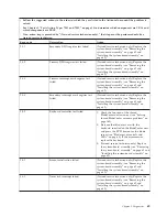
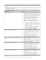
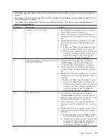
Follow the suggested actions in the order in which they are listed in the Action column until the problem is
solved.
v
See Chapter 3, “Parts listing, Types 7901 and 7902,” on page 19 to determine which components are CRUs and
which components are FRUs.
v
If an action step is preceded by “(Trained service technician only),” that step must be performed only by a
trained service technician.
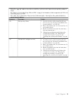
Error code
Description
Action
185
Corrupted boot sequence
1.
Run the Setup Utility program, select
Load
Default Settings
, and save the settings (see
“Using the Setup Utility program” on page 11).
2.
(Trained service technician only) Replace the
system-board assembly (see “Removing the
system-board assembly” on page 62 and
“Installing the system-board assembly” on page
62).
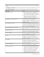
186
Security hardware control logic error
(Trained service technician only) Replace the
system-board assembly (see “Removing the
system-board assembly” on page 62 and “Installing
the system-board assembly” on page 62).
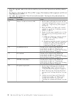
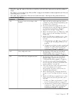
187
VPD Serial Number not set
(Trained service technician only) Replace the
system-board assembly (see “Removing the
system-board assembly” on page 62 and “Installing
the system-board assembly” on page 62).
188
Bad EEPROM CRC #2
(Trained service technician only) Replace the
system-board assembly (see “Removing the
system-board assembly” on page 62 and “Installing
the system-board assembly” on page 62).
189
Three attempts to enter the incorrect
password.
Restart the blade server, run the Setup Utility
program, and change the power-on password (see
“Using the Setup Utility program” on page 11).
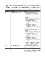
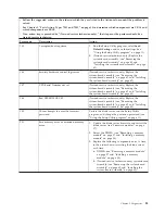
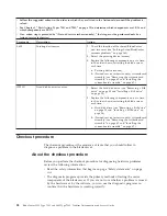
201
Base memory error or extended memory
error.
1.
Update the blade server firmware and restart the
blade server (see “Firmware updates” on page
17).
2.
Reseat the DIMMs (see “Removing a memory
module” on page 37 and “Installing a memory
module” on page 38).
3.
Replace the following components one at a time,
in the order shown, restarting the blade server
each time:
a.
DIMMs (see “Removing a memory module”
on page 37 and “Installing a memory
module” on page 38)
b.
(Trained service technician only) system-board
assembly (see “Removing the system-board
assembly” on page 62 and “Installing the
system-board assembly” on page 62)
Chapter 5. Diagnostics
83
Содержание LS42 - BladeCenter - 7902
Страница 1: ...BladeCenter LS22 Type 7901 and LS42 Type 7902 Problem Determination and Service Guide...
Страница 2: ......
Страница 3: ...BladeCenter LS22 Type 7901 and LS42 Type 7902 Problem Determination and Service Guide...
Страница 12: ...x BladeCenter LS22 Type 7901 and LS42 Type 7902 Problem Determination and Service Guide...
Страница 76: ...64 BladeCenter LS22 Type 7901 and LS42 Type 7902 Problem Determination and Service Guide...
Страница 192: ...180 BladeCenter LS22 Type 7901 and LS42 Type 7902 Problem Determination and Service Guide...
Страница 193: ......
Страница 194: ...Part Number 49Y0107 Printed in USA 1P P N 49Y0107...

