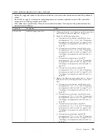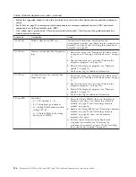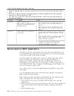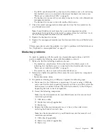
Damaged data in CMOS memory or damaged BIOS code can cause undetermined
problems. To reset the CMOS data, remove and replace the battery to override the
power-on password and clear the CMOS memory; see “Removing the battery” on
page 48 and “Installing the battery” on page 48. If you suspect that the BIOS code
is damaged, see “Recovering from a BIOS update failure” on page 158.
Check the LEDs on all the power supplies of the BladeCenter unit in which the
blade server is installed. If the LEDs indicate that the power supplies are working
correctly and reseating the blade server does not correct the problem, complete the
following steps:
1.
Make sure that the control panel connector is correctly seated on the system
board (see “System-board connectors” on page 7 for the location of the
connector).
2.
If no LEDs on the control panel are working, replace the bezel assembly (see
“Removing the bezel assembly” on page 33 and “Installing the bezel assembly”
on page 34); then, try to turn on the blade server from the management module
(see the documentation for the BladeCenter unit and management module for
more information).
3.
Turn off the blade server (see “Turning off the blade server” on page 6).
4.
Remove the blade server from the BladeCenter unit and remove the cover (see
“Removing the blade server from a BladeCenter unit” on page 27 and
“Removing the blade server cover” on page 29).
5.
Remove or disconnect the following devices, one at a time, until you find the
failure. Reinstall, turn on, and reconfigure the blade server each time.
v
MPE unit, if one is installed (see “Removing an expansion unit” on page 31)
v
I/O-expansion cards (see “Removing an I/O expansion card” on page 39)
v
Hard disk drive (see “Removing a SAS drive” on page 35)
v
Memory modules (see “Removing a memory module” on page 37). The
minimum configuration requirement is 2 GB (two 1 GB DIMMs on the
system board).
The following minimum configuration is required for the blade server to start:
v
System-board assembly
v
One microprocessor
v
Two 1 GB DIMMs
v
A functioning BladeCenter unit
6.
Install and turn on the blade server (see “Turning on the blade server” on page
5). If the problem remains, suspect the following components in the following
order:
a.
DIMM
b.
Microprocessor
c.
System-board assembly
If the problem is solved when you remove an I/O-expansion card from the blade
server but the problem recurs when you reinstall the same card, suspect the
I/O-expansion card; if the problem recurs when you replace the card with a
different one, suspect the system board.
If you suspect a networking problem and the blade server passes all the system
tests, suspect a network cabling problem that is external to the system.
Chapter 5. Diagnostics
165
Содержание LS42 - BladeCenter - 7902
Страница 1: ...BladeCenter LS22 Type 7901 and LS42 Type 7902 Problem Determination and Service Guide...
Страница 2: ......
Страница 3: ...BladeCenter LS22 Type 7901 and LS42 Type 7902 Problem Determination and Service Guide...
Страница 12: ...x BladeCenter LS22 Type 7901 and LS42 Type 7902 Problem Determination and Service Guide...
Страница 76: ...64 BladeCenter LS22 Type 7901 and LS42 Type 7902 Problem Determination and Service Guide...
Страница 192: ...180 BladeCenter LS22 Type 7901 and LS42 Type 7902 Problem Determination and Service Guide...
Страница 193: ......
Страница 194: ...Part Number 49Y0107 Printed in USA 1P P N 49Y0107...

