background image

v

Remove the device from its package and install it directly into the blade server
without setting it down. If it is necessary to set down the device, put it back into
its static-protective package. Do not place the device on the blade server cover
or on a metal surface.

v

Take additional care when you handle devices during cold weather. Heating
reduces indoor humidity and increases static electricity.

Returning a device or component

If you are instructed to return a device or component, follow all packaging
instructions, and use any packaging materials for shipping that are supplied to
you.

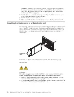
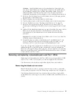
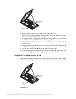
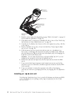
Removing the blade server from a BladeCenter unit

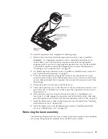
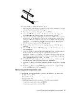
The following illustration shows how to remove an LS22 Type 7901 blade server
from a Type 8677 BladeCenter unit. The procedure for removing the LS42 Type
7902 blade server and MPE is the same. The appearance of your BladeCenter unit
might be different. See the documentation for your BladeCenter unit for additional
information.

Release handles
(open)

Attention:

v

To maintain proper system cooling, do not operate the BladeCenter unit without
a blade server, expansion unit, or filler installed in each blade bay.

v

When you remove the blade server, note the bay number. Reinstalling a blade
server into a different bay from the one it was removed from might have
unintended consequences. Some configuration information and update options
are established according to bay number; if you reinstall the blade server into a
different bay, you might have to reconfigure the blade server.

To remove the blade server, complete the following steps:

1.

Read the safety information that begins on page “Safety statements” on page
viii and “Installation guidelines” on page 25.

2.

If the blade server is operating, shut down the operating system.

3.

Press the power-control button (behind the blade server control panel door) to
turn off the blade server (see “Turning off the blade server” on page 6 for more
information).

Chapter 4. Removing and replacing blade server components

27

Содержание LS42 - BladeCenter - 7902

Страница 1: ...BladeCenter LS22 Type 7901 and LS42 Type 7902 Problem Determination and Service Guide...

Страница 2: ......

Страница 3: ...BladeCenter LS22 Type 7901 and LS42 Type 7902 Problem Determination and Service Guide...

Страница 4: ...page 169 and the Warranty and Support Information document on the IBM BladeCenter Documentation CD Sixth Edition July 2009 Copyright International Business Machines Corporation 2009 US Government Use...

Страница 5: ...31 Installing an expansion unit 32 Removing the bezel assembly 33 Installing the bezel assembly 34 Removing a SAS drive 35 Installing a SAS drive 36 Removing a memory module 37 Installing a memory mod...

Страница 6: ...on 167 Getting help and information from the World Wide Web 168 Software service and support 168 Hardware service and support 168 IBM Taiwan product service 168 Notices 169 Trademarks 169 Important no...

Страница 7: ...ten Ennen kuin asennat t m n tuotteen lue turvaohjeet kohdasta Safety Information Avant d installer ce produit lisez les consignes de s curit Vor der Installation dieses Produkts die Sicherheitshinwei...

Страница 8: ...ry power Primary voltage on the frame can cause serious or fatal electrical shock v Explosive hazards such as a damaged CRT face or a bulging capacitor v Mechanical hazards such as loose or missing ha...

Страница 9: ...Disconnect all power before you perform a mechanical inspection work near power supplies or remove or install main units v Before you work on the equipment disconnect the power cord If you cannot disc...

Страница 10: ...ct during an electrical storm v Connect all power cords to a properly wired and grounded electrical outlet v Connect to properly wired outlets any equipment that will be attached to this product v Whe...

Страница 11: ...tery contains lithium and can explode if not properly used handled or disposed of Do not v Throw or immerse into water v Heat to more than 100 C 212 F v Repair or disassemble Dispose of the battery as...

Страница 12: ...x BladeCenter LS22 Type 7901 and LS42 Type 7902 Problem Determination and Service Guide...

Страница 13: ...ed only by trained service technicians For information about the terms of the warranty and getting service and assistance see the Warranty and Support Information document Related documentation In add...

Страница 14: ...hese notices provide information or advice that might help you avoid inconvenient or problem situations v Attention These notices indicate potential damage to programs devices or data An attention not...

Страница 15: ...ice such as the IBM USB key for VMware ESXi Size v Height 24 5 cm 9 7 inches v Depth 44 6 cm 17 6 inches v Width Single width models 2 9 cm 1 14 inches Double width models 4 8 cm 2 28 inches v Maximum...

Страница 16: ...han one blade bay is identified by the lowest bay number that it occupies If there is no response when you press the KVM select button you can use the management module Web interface to determine whet...

Страница 17: ...ement module Web interface or through IBM Director Console Blade error LED When this amber LED is lit it indicates that a system error has occurred in the blade server The blade error LED will turn of...

Страница 18: ...nit Shut down the operating system before you turn off the blade server See the operating system documentation for information about shutting down the operating system The blade server can be turned o...

Страница 19: ...System board connectors The following illustration shows the connectors on the blade server system board The following illustration shows the connectors on the MPE unit Chapter 1 Introduction 7...

Страница 20: ...before you removed the blade server from the BladeCenter unit SW4 Switch block 4 has four switches v 1 Debug serial port Open Disable default Closed Enable v 2 Flash bank select Open Primary default C...

Страница 21: ...e system board can be lit for a maximum of two minutes System board LEDs The following illustration shows the LEDs on the blade server system board To see these LEDs remove the blade server from the B...

Страница 22: ...path diagnostics switch The following illustration shows the LEDs on the MPE unit To see these LEDs remove the blade server from the BladeCenter unit open the cover and press the light path diagnostic...

Страница 23: ...ram is part of the BIOS code in the blade server Use it to select the boot protocol and other boot options and to select a power management option For information about using this utility program see...

Страница 24: ...model of the blade server the serial number and the revision level or issue date of the BIOS and diagnostics code that are stored in electrically erasable programmable ROM EEPROM v Devices and I O Por...

Страница 25: ...ect this choice to change settings for advanced hardware features Important The blade server might malfunction if these settings are incorrectly configured Follow the instructions on the screen carefu...

Страница 26: ...g the ServerGuide Setup and Installation CD The ServerGuide Setup and Installation CD contains a setup and installation program that is designed for your blade server The ServerGuide program detects t...

Страница 27: ...igure any supported IBM blade server model The setup program provides a list of tasks that are required to set up the blade server Note Features and functions can vary slightly with different versions...

Страница 28: ...systems support 2 Under Product support click BladeCenter 3 From the menu on the left side of the page click BladeCenter support search 4 From the Task menu select Install 5 From the Product family li...

Страница 29: ...ce driver to enable the blade server operating system to address the Ethernet controller For device drivers and information about configuring the Ethernet controller see the Broadcom NetXtreme Gigabit...

Страница 30: ...I Logic Configuration Utility program to perform the following tasks v Set the SAS device scan order v Set the SAS ID for the controller v Manage the SAS RAID configuration To start the LSI Logic Conf...

Страница 31: ...ade periodically to the IBM Web site The actual procedure might vary slightly from what is described in this document 1 Go to http www ibm com systems support 2 Under Product support click BladeCenter...

Страница 32: ...If IBM installs a Tier 1 CRU at your request you will be charged for the installation v Tier 2 customer replaceable unit You may install a Tier 2 CRU yourself or request IBM to install it at no addit...

Страница 33: ...essor quad core Opteron 8347 HE 1 9 GHz 79W type 7902 model 3Qx 44X1550 6 Microprocessor quad core Opteron 2376 HE 2 3 GHz 79 W type 7901 model 3Lx 46M6878 6 Microprocessor quad core Opteron 8374 HE 2...

Страница 34: ...iniBand Host Channel Adapter expansion card option 32R1763 Cisco Systems InfiniBand HCA expansion card option 32R1899 Dust cover microprocessor all models 40K5936 Emulex 4 Gb SFF Fibre Channel expansi...

Страница 35: ...sion option 41Y8525 QLogic SFF 4 Gb Fibre Channel option 26R0893 Microsoft Windows Server 2008 Datacenter 32 64 bit Multilingual 49Y0222 Microsoft Windows Server 2008 Datacenter 32 64 bit Simplified C...

Страница 36: ...t 1 4 Processors Simplified Chinese 49Y0893 Windows Server 2008 Standard Edition 32 64 Bit 1 4 Processors Traditional Chinese 49Y0894 Windows Server 2008 Enterprise Edition 32 64 Bit 1 8 Processors Mu...

Страница 37: ...ove or replace a component read the following information v Read the safety information that begins on page Safety statements on page viii and the guidelines in Handling static sensitive devices on pa...

Страница 38: ...s only one microprocessor it must be installed in microprocessor socket 1 v Do not operate the BladeCenter unit without a blade server expansion unit or filler installed in each blade bay See the docu...

Страница 39: ...See the documentation for your BladeCenter unit for additional information Release handles open Attention v To maintain proper system cooling do not operate the BladeCenter unit without a blade serve...

Страница 40: ...7 BladeCenter unit The procedure for installing the double width type of blade server is the same The appearance of your BladeCenter unit might be different see the documentation for your BladeCenter...

Страница 41: ...in any way block the ventilation holes on the blade server 9 Reinstall the bezel assembly on the BladeCenter T unit BladeCenter T unit only For detailed instructions for reinstalling the bezel assembl...

Страница 42: ...ss the blade cover release on each side of the blade server or expansion unit and lift the cover open 5 Lift the cover from the blade server and store it for future use 6 If you are instructed to retu...

Страница 43: ...or instructions 4 Lower the cover so that the slots at the rear slide down onto the pins at the rear of the blade server Before closing the cover check that all components are installed and seated cor...

Страница 44: ...the expansion unit from the blade server Attention Do not rotate the expansion unit open further than 90 to avoid damage to the connectors at the rear of the blade server 6 Rotate the expansion unit o...

Страница 45: ...t then remove the expansion unit from the package 4 Orient the expansion unit above the blade server 5 Lower the expansion unit so that the slots at the rear slide down onto the cover pins at the rear...

Страница 46: ...cm 0 5 inch 5 If you are removing the bezel assembly from a blade server disconnect the control panel cable from the control panel connector by lifting up on the control panel cable If you are removin...

Страница 47: ...icks into place Note Do not allow the control panel cable to become caught between the bezel assembly and the air baffle or blade server chassis 3 Install the MPE unit or expansion unit if you removed...

Страница 48: ...drive out of the drive tray v If you are removing a SAS drive from SAS connector 1 slide the drive forward to disengage it from the connector at the rear of the drive tray then lift the drive out of...

Страница 49: ...n page 29 4 If you are removing a DIMM from the blade server and an MPE unit or expansion unit is installed remove the MPE unit see Removing an expansion unit on page 31 5 Locate the DIMM connectors s...

Страница 50: ...Note Only the BladeCenter LS42 Type 7902 with an MPE installed can support more than two microprocessors Number of micro processors Blade server MPE DIMM connector DIMM connector 1 2 3 4 5 6 7 8 1 2...

Страница 51: ...ystem board 7 Insert the DIMM by pressing the DIMM along the guides into the connector Make sure that the retaining clips snap into the closed positions Attention If there is a gap between the DIMM an...

Страница 52: ...oving the expansion card from the blade server and an MPE unit or expansion unit is installed remove the MPE unit see Removing an expansion unit on page 31 5 Gently pivot the wide end of the card out...

Страница 53: ...e wide end of the card out of the expansion card connectors then slide the notched end of the card out of the raised hook on the expansion card bracket and lift the card out of the blade server 6 If y...

Страница 54: ...complete the following steps 1 Read the safety information that begins on page Safety statements on page viii and Installation guidelines on page 25 2 If the blade server is installed in a BladeCenter...

Страница 55: ...High speed HSDC v Combination form factor that includes the following two card types Combination form factor horizontal CFFh Combination form factor vertical CFFv The following table lists the combin...

Страница 56: ...actor expansion card SFF X X X Standard form factor expansion card CFFv X X X SFF Standard form factor expansion card X X SFF SFF X X X SFF CFFv X X X CFFh CFFv Standard form factor expansion card X X...

Страница 57: ...the installation of the expansion card see the documentation that comes with the expansion card 4 Install the MPE unit or expansion unit if you removed one while you removed the expansion card see Ins...

Страница 58: ...alling a high speed expansion card The following illustration shows how to install a high speed expansion card in the blade server installing a high speed expansion card in the MPE unit is similar To...

Страница 59: ...mponent then remove the expansion card from the package 2 Install the CFFv card The following illustration shows how to install a CFFv expansion card in the blade server installing a CFFv expansion ca...

Страница 60: ...ge 7 6 Use one finger to press the top of the battery clip away from the battery The battery pops up when it is released 7 Use your thumb and index finger to lift the battery from the socket 8 Dispose...

Страница 61: ...a Tilt the battery so that you can insert it into the socket on the side opposite the battery clip b Press the battery down into the socket until it clicks into place Make sure the battery clip holds...

Страница 62: ...ing instructions and use any packaging materials for shipping that are supplied to you Installing the LS22 optimizer The following illustration shows how to install the LS22 optimizer card from the bl...

Страница 63: ...29 4 If an MPE unit is installed remove the MPE unit see Removing an expansion unit on page 31 5 If any of the following expansion cards are installed in the blade server remove them v Small form fact...

Страница 64: ...that comes with the card 4 If you removed any of the following expansion cards while you removed the concurrent KVM card reinstall them v Small form factor card see Installing a small form factor exp...

Страница 65: ...embly on page 33 6 Slide the USB flash drive out of the USB connector on the system board 7 If you are instructed to return the USB flash drive follow all packaging instructions and use any packaging...

Страница 66: ...ing the SAS drive tray The following illustration shows how to remove the SAS drive tray from the blade server To remove the SAS drive tray complete the following steps 1 Read the safety information t...

Страница 67: ...t secure the drive tray to the system board 4 If you removed the hard disk drive while you removed the drive tray reinstall it see Installing a SAS drive on page 36 5 Install the MPE unit or expansion...

Страница 68: ...ctor expansion card on page 40 6 Locate the expansion card bracket in front of SAS connector 1 see System board connectors on page 7 7 Use a screwdriver to remove the two screws that attach the expans...

Страница 69: ...ion unit on page 32 7 Install the blade server cover see Installing the blade server cover on page 30 8 Install the blade server into the BladeCenter unit see Installing the blade server in a BladeCen...

Страница 70: ...nd heat sink from the blade server the procedure for removing a microprocessor and heat sink from the MPE unit is similar To remove a microprocessor and heat sink complete the following steps 1 Read t...

Страница 71: ...the locking lever on the microprocessor socket from its closed and locked position until it stops in the fully open position approximately a 135 angle 9 Rotate the microprocessor retainer to the open...

Страница 72: ...er Attention Handle the microprocessor only by its edges Do not touch the contacts on the bottom of the microprocessor or in the microprocessor socket Touching these contacts might result in permanent...

Страница 73: ...ntaminated contact your service technician a Remove the plastic protective cover from the bottom of the heat sink b Make sure that the thermal material is still on the bottom of the heat sink then ali...

Страница 74: ...he bezel assembly on page 33 6 Remove all of the installed components in the following list from the system board assembly then place them on a static protective surface or install them on the new sys...

Страница 75: ...on cards See Installing an I O expansion card on page 43 v LS22 Type 7901 and single width LS42 Type 7902 only LS22 optimizer See Installing the LS22 optimizer on page 50 2 Install the bezel assembly...

Страница 76: ...64 BladeCenter LS22 Type 7901 and LS42 Type 7902 Problem Determination and Service Guide...

Страница 77: ...ates beep codes and messages to indicate successful test completion or the detection of a problem See POST for more information v Troubleshooting tables These tables list problem symptoms and actions...

Страница 78: ...ror codes or light path diagnostics LEDs indicate a microprocessor error the error might be in a microprocessor or in a microprocessor socket See Microprocessor problems on page 93 for information abo...

Страница 79: ...time a DIMMs see Removing a memory module on page 37 and Installing a memory module on page 38 b Trained service technician only system board assembly see Removing the system board assembly on page 62...

Страница 80: ...on page 62 and Installing the system board assembly on page 62 c Trained service technician only MPE board assembly if one is installed see Removing the system board assembly on page 62 and Installin...

Страница 81: ...ard assembly on page 62 2 1 4 Secondary interrupt mask register test failed Trained service technician only Replace the system board assembly see Removing the system board assembly on page 62 and Inst...

Страница 82: ...ver each time a Battery see Removing the battery on page 48 and Installing the battery on page 48 b Trained service technician only system board assembly see Removing the system board assembly on page...

Страница 83: ...the order shown restarting the blade server each time a DIMMs see Removing a memory module on page 37 and Installing a memory module on page 38 b Trained service technician only system board assembly...

Страница 84: ...s If a blade server is moved from one bay to another the management module event log reports messages for that blade server according to the new bay number messages for that blade server that were gen...

Страница 85: ...X slots I O slots note that the error logs report the PCI X buses numerically The numerical assignments vary depending on the configuration You can check the assignments by running the Setup Utility...

Страница 86: ...card see Removing a concurrent KVM feature card on page 51 and Installing a concurrent KVM feature card on page 51 BEM 1 fault 1 Reseat the following components one at a time in the order shown resta...

Страница 87: ...nit on page 32 2 Replace the expansion unit system board see Removing an expansion unit on page 31 and Installing an expansion unit on page 32 Firmware BIOS halted System management bus error Update t...

Страница 88: ...tem board assembly on page 62 Microprocessor temperature warning 1 Make sure that the blade server is sufficiently cooled see System reliability guidelines on page 26 2 Make sure that the front bezel...

Страница 89: ...ed by the BladeCenter unit in which it is installed see the IBM BladeCenter Management Module User s Guide for more information Firmware BIOS ROM corruption detected Update the BIOS code see Firmware...

Страница 90: ...technician only that step must be performed only by a trained service technician Error message Action Hard drive xx removal detected Replace SAS drive xx see Removing a SAS drive on page 35 and Instal...

Страница 91: ...rocessor 2 see Removing a microprocessor and heat sink on page 57 and Installing a microprocessor and heat sink on page 59 3 Replace the following components one at a time in the order shown restartin...

Страница 92: ...moving a microprocessor and heat sink on page 57 and Installing a microprocessor and heat sink on page 59 2 Replace the following components one at a time in the order shown restarting the server each...

Страница 93: ...Run the Setup Utility program select Load Default Settings and save the settings see Using the Setup Utility program on page 11 2 Reseat the battery see Removing the battery on page 48 and Installing...

Страница 94: ...he system board assembly on page 62 and Installing the system board assembly on page 62 175 Bad EEPROM CRC 1 Trained service technician only Replace the system board assembly see Removing the system b...

Страница 95: ...t set Trained service technician only Replace the system board assembly see Removing the system board assembly on page 62 and Installing the system board assembly on page 62 188 Bad EEPROM CRC 2 Train...

Страница 96: ...If you have installed a USB keyboard run the Setup Utility program and enable keyboardless operation to prevent the POST error message 301 from being displayed during startup see Using the Setup Utili...

Страница 97: ...e the instructions for your diskette drive 3 Replace the diskette drive see the instructions for your diskette drive 4 Trained service technician only Replace the system board assembly see Removing th...

Страница 98: ...Installing a microprocessor and heat sink on page 59 b Trained service technician only Microprocessor 2 see Removing a microprocessor and heat sink on page 57 and Installing a microprocessor and heat...

Страница 99: ...age 36 b Trained service technician only system board assembly see Removing the system board assembly on page 62 and Installing the system board assembly on page 62 2462 Video configuration error 1 Ru...

Страница 100: ...ve see Removing a SAS drive on page 35 and Installing a SAS drive on page 36 2 Replace the following components one at a time in the order shown restarting the blade server each time a Hard disk drive...

Страница 101: ...5 Make sure that the blade server has control of the video the KVM button is lit If the blade server does not start see Troubleshooting tables 3 Record any POST beep codes that sound or POST error me...

Страница 102: ...ained service technician Symptom Action Not all drives are recognized by the hard disk drive diagnostic test 1 Remove the drive that is indicated by the diagnostic tests see Removing a SAS drive on pa...

Страница 103: ...ich they are listed in the Action column until the problem is solved v See Chapter 3 Parts listing Types 7901 and 7902 on page 19 to determine which components are CRUs and which components are FRUs v...

Страница 104: ...for error message 289 see Error logs on page 72 v If a DIMM was disabled by a system management interrupt SMI replace the DIMM see Removing a memory module on page 37 and Installing a memory module o...

Страница 105: ...heat sink on page 57 and Installing a microprocessor and heat sink on page 59 b Trained service technician only Microprocessor 2 see Removing a microprocessor and heat sink on page 57 and Installing a...

Страница 106: ...ervice technician only Replace the system board assembly see Removing the system board assembly on page 62 and Installing the system board assembly on page 62 The monitor has screen jitter or the scre...

Страница 107: ...until the problem is solved v See Chapter 3 Parts listing Types 7901 and 7902 on page 19 to determine which components are CRUs and which components are FRUs v If an action step is preceded by Trained...

Страница 108: ...er see Removing the blade server from a BladeCenter unit on page 27 and Installing the blade server in a BladeCenter unit on page 28 2 Check the function of the shared BladeCenter unit resources see S...

Страница 109: ...the system board assembly on page 62 System under recommended voltage for 12v 1 Reseat the blade server see Removing the blade server from a BladeCenter unit on page 27 and Installing the blade serve...

Страница 110: ...es not work and the reset button does work 1 Reseat the control panel connector see Removing the bezel assembly on page 33 and Installing the bezel assembly on page 34 2 Replace the following componen...

Страница 111: ...ng the blade server from a BladeCenter unit on page 27 and Installing the blade server in a BladeCenter unit on page 28 5 If you just installed a device in the blade server remove it and restart the b...

Страница 112: ...essor see Removing a microprocessor and heat sink on page 57 and Installing a microprocessor and heat sink on page 59 3 Trained service technician only Replace the system board assembly see Removing t...

Страница 113: ...f the SUSE Linux operating system is installed remotely onto a blade server that is not the current owner of the media tray CD or DVD drive diskette drive and USB port SUSE Linux detects the CD or DVD...

Страница 114: ...ogram See the ServerGuide Setup and Installation CD label for a list of supported operating system versions The operating system cannot be installed the option is not available Make sure that the blad...

Страница 115: ...e Universal Serial Bus USB port problems The USB ports are shared BladeCenter unit resources First make sure that the USB ports are assigned to the blade server then see the following table and Solvin...

Страница 116: ...hat information about a suboptimal condition in the blade server is available in the BMC log or in the management module event log v If the blade error LED is lit it indicates that an error has occurr...

Страница 117: ...SBRD TEMP LP 1 NMI error LED Microprocessor mismatch error LED System board error LED Over temperature error LED Light path diagnostics LED Light path diagnostics switch The following illustration sh...

Страница 118: ...Ds are lit on the blade server system board MPE unit and light path diagnostics panels Using this information and the information in Light path diagnostics LEDs can often provide enough information to...

Страница 119: ...IMM at a time until the error is corrected LP1 v On the blade server light path diagnostics panel The light path diagnostics LEDs on the blade server system board have power v On the MPE unit light pa...

Страница 120: ...m board assembly on page 62 v Trained service technician only If the lit LED is on the MPE unit light path diagnostics panel replace the MPE board assembly see Removing the system board assembly on pa...

Страница 121: ...orage drives Additionally DSA creates a merged log that includes events from all collected logs You can output all the collected information as a compressed XML file that you can send to IBM service a...

Страница 122: ...If the diagnostic programs do not detect any hardware errors but the problem remains during normal server operations a software error might be the cause If you suspect a software problem see the infor...

Страница 123: ...generate and suggested actions to correct the detected problems Follow the suggested actions in the order in which they are listed in the action column In the error codes x can be any numeral or lette...

Страница 124: ...evel is shown in the DSA event log in the Firmware VPD section for this component For the latest level of firmware go to http www ibm com support docview wss uid psg1 MIGR 4JTS2T and select your syste...

Страница 125: ...nent For the latest level of firmware go to http www ibm com support docview wss uid psg1 MIGR 4JTS2T and select your system to display a matrix of available firmware 5 Run the test again 6 Turn off a...

Страница 126: ...ain 4 Make sure that the system firmware is at the latest level The installed firmware level is shown in the DSA event log in the Firmware VPD section for this component For the latest level of firmwa...

Страница 127: ...server from a BladeCenter unit on page 27 and Installing the blade server in a BladeCenter unit on page 28 2 Run the test again 3 Make sure that the DSA code is at the latest level For the latest lev...

Страница 128: ...est again 3 Make sure that the DSA code is at the latest level For the latest level of DSA code go to http www ibm com support docview wss uid psg1SERV DSA 4 Make sure that the BMC firmware is at the...

Страница 129: ...the DSA code is at the latest level For the latest level of DSA code go to http www ibm com support docview wss uid psg1SERV DSA 4 Make sure that the BMC firmware is at the latest level The installed...

Страница 130: ...a BladeCenter unit on page 27 and Installing the blade server in a BladeCenter unit on page 28 2 Run the test again 3 Make sure that the DSA code is at the latest level For the latest level of DSA cod...

Страница 131: ...adeCenter unit on page 28 2 Run the test again 3 Make sure that the DSA code is at the latest level For the latest level of DSA code go to http www ibm com support docview wss uid psg1SERV DSA 4 Make...

Страница 132: ...from a BladeCenter unit on page 27 and Installing the blade server in a BladeCenter unit on page 28 2 Run the test again 3 Make sure that the DSA code is at the latest level For the latest level of D...

Страница 133: ...server see Removing the blade server from a BladeCenter unit on page 27 and Installing the blade server in a BladeCenter unit on page 28 2 Make sure that the DSA code is at the latest level For the la...

Страница 134: ...rom a BladeCenter unit on page 27 and Installing the blade server in a BladeCenter unit on page 28 2 Run the test again 3 Make sure that the DSA code is at the latest level For the latest level of DSA...

Страница 135: ...the blade server see Removing the blade server from a BladeCenter unit on page 27 and Installing the blade server in a BladeCenter unit on page 28 2 Run the test again 3 Make sure that the DSA code is...

Страница 136: ...nd Installing the blade server in a BladeCenter unit on page 28 2 Run the test again 3 Make sure that the DSA code is at the latest level For the latest level of DSA code go to http www ibm com suppor...

Страница 137: ...Removing the blade server from a BladeCenter unit on page 27 and Installing the blade server in a BladeCenter unit on page 28 2 Make sure that the DSA code is at the latest level For the latest level...

Страница 138: ...tes invalid machine ID that is not supported 1 Turn off and restart the system 2 Run the test again 3 Make sure that the system BIOS code is at the latest level The installed firmware level is shown i...

Страница 139: ...t the latest level For the latest level of DSA code go to http www ibm com support docview wss uid psg1SERV DSA 4 Make sure that the system BIOS code is at the latest level The installed firmware leve...

Страница 140: ...shown in the DSA event log in the Firmware VPD section for this component For the latest level of firmware go to http www ibm com support docview wss uid psg1 MIGR 4JTS2T and select your system to di...

Страница 141: ...st level The installed firmware level is shown in the DSA event log in the Firmware VPD section for this component For the latest level of firmware go to http www ibm com support docview wss uid psg1...

Страница 142: ...de is at the latest level The installed firmware level is shown in the DSA event log in the Firmware VPD section for this component For the latest level of firmware go to http www ibm com support docv...

Страница 143: ...atest level The installed firmware level is shown in the DSA event log in the Firmware VPD section for this component For the latest level of firmware go to http www ibm com support docview wss uid ps...

Страница 144: ...re level is shown in the DSA event log in the Firmware VPD section for this component For the latest level of firmware go to http www ibm com support docview wss uid psg1 MIGR 4JTS2T and select your s...

Страница 145: ...at the latest level The installed firmware level is shown in the DSA event log in the Firmware VPD section for this component For the latest level of firmware go to http www ibm com support docview w...

Страница 146: ...installed firmware level is shown in the DSA event log in the Firmware VPD section for this component For the latest level of firmware go to http www ibm com support docview wss uid psg1 MIGR 4JTS2T a...

Страница 147: ...of DSA code go to http www ibm com support docview wss uid psg1SERV DSA 2 Make sure that the system BIOS code is at the latest level The installed firmware level is shown in the DSA event log in the...

Страница 148: ...p www ibm com support docview wss uid psg1SERV DSA 3 Make sure that the system BIOS code is at the latest level The installed firmware level is shown in the DSA event log in the Firmware VPD section f...

Страница 149: ...tem 2 Run the test again 3 Make sure that the DSA code is at the latest level For the latest level of DSA code go to http www ibm com support docview wss uid psg1SERV DSA 4 Run the test again 5 Run th...

Страница 150: ...ng at both ends for loose or broken connections or damage to the cable Replace the cable if it is damaged 4 Run the test again 5 For additional troubleshooting information go to http www ibm com suppo...

Страница 151: ...n the test again 3 Insert a new CD or DVD into the drive and wait for 15 seconds for the media to be recognized 4 Run the test again 5 Check the drive cabling at both ends for loose or broken connecti...

Страница 152: ...psg1MIGR 41559 6 Run the test again 7 Replace the CD or DVD drive 8 If the failure remains collect the data from the DSA event log and send it to IBM Service For information about contacting and sendi...

Страница 153: ...st LEDs Passed The device passed the test No action is required 405 901 xxx Broadcom Ethernet device Test control registers Failed 1 Make sure that the component firmware is at the latest level The in...

Страница 154: ...firmware level is shown in the DSA event log in the Firmware VPD section for this component For the latest level of firmware go to http www ibm com support docview wss uid psg1 MIGR 4JTS2T and select...

Страница 155: ...e latest level The installed firmware level is shown in the DSA event log in the Firmware VPD section for this component For the latest level of firmware go to http www ibm com support docview wss uid...

Страница 156: ...www ibm com support docview wss uid psg1 MIGR 4JTS2T and select your system to display a matrix of available firmware 2 Run the test again 3 Check the interrupt assignments in the PCI Hardware section...

Страница 157: ...iew wss uid psg1 MIGR 4JTS2T and select your system to display a matrix of available firmware 2 Run the test again 3 Check the interrupt assignments in the PCI Hardware section of the DSA event log If...

Страница 158: ...component firmware is at the latest level The installed firmware level is shown in the DSA event log in the Firmware VPD section for this component For the latest level of firmware go to http www ibm...

Страница 159: ...s at the latest level The installed firmware level is shown in the DSA event log in the Firmware VPD section for this component For the latest level of firmware go to http www ibm com support docview...

Страница 160: ...ware level is shown in the DSA event log in the Firmware VPD section for this component For the latest level of firmware go to http www ibm com support docview wss uid psg1 MIGR 4JTS2T and select your...

Страница 161: ...d contains this component If the error is caused by an adapter replace the adapter Check the PCI Information and Network Settings information in the DSA event log to determine the physical location of...

Страница 162: ...al SAS interface test Trained service technician only Replace the system board assembly see Removing the system board assembly on page 62 and Installing the system board assembly on page 62 035 xxx 09...

Страница 163: ...Trained service technician only MPE microprocessor 1 if n 4 or 5 see Removing a microprocessor and heat sink on page 57 and Installing a microprocessor and heat sink on page 59 d Trained service tech...

Страница 164: ...the system board assembly on page 62 165 198 000 Service Processor Aborted 1 Run the diagnostic test again see Running the diagnostic programs on page 109 2 Correct the other error conditions that mi...

Страница 165: ...anagement Aborted 1 Remove the blade server from BladeCenter unit wait 30 seconds and reseat it in the BladeCenter unit then run the test again see Removing the blade server from a BladeCenter unit on...

Страница 166: ...1 and Installing the blade server cover on page 30 4 Run the test again see Running the diagnostic programs on page 109 5 Trained service technician only If the error does not repeat replace the MPE b...

Страница 167: ...ystem board assembly on page 62 166 nnn 001 System Management Failed BMC indicates failure in self test Note 1 nnn 300 to 320 2 nnn 400 to 424 excluding 403 and 419 to 422 1 Remove the blade server fr...

Страница 168: ...mware updates on page 17 4 See the error log for additional information 201 199 xxx Unexpected error Test aborted See Diagnostics logs 1 Restart the server see Turning off the blade server on page 6 a...

Страница 169: ...sor n is on the MPE see Removing an expansion unit on page 31 and Installing an expansion unit on page 32 c Trained service technician only System board if microprocessor n is on the blade server see...

Страница 170: ...age 62 and Installing the system board assembly on page 62 Recovering from a BIOS update failure The blade server has an advanced recovery feature that will automatically switch to a backup BIOS page...

Страница 171: ...server on page 5 The power on self test POST starts 12 Select 1 Update POST BIOS from the menu that contains various flash update options Attention Do not type Y when you are prompted to back up the R...

Страница 172: ...BladeCenter resource problems If the problem is thought to be with a shared resource see the Problem Determination and Service Guide or the Hardware Maintenance Manual and Troubleshooting Guide for y...

Страница 173: ...ke sure that the following conditions are met v The media tray select button LED on the front of the blade server is lit indicating that the blade server is connected to the shared media tray see Blad...

Страница 174: ...ee the documentation for your BladeCenter unit for removal and installation procedures 1 Removable media drive cable if applicable 2 Removable media drive 3 Media tray cable if applicable 4 Media tray...

Страница 175: ...he documentation for your BladeCenter unit If these steps do not solve the problem it is likely a problem with the blade server See Network connection problems on page 94 Power problems To check for p...

Страница 176: ...any diskette drive is at least 76 mm 3 in 2 Check for correct management module operation see the documentation for your BladeCenter unit Note Some BladeCenter unit types have several management modu...

Страница 177: ...move the cover see Removing the blade server from a BladeCenter unit on page 27 and Removing the blade server cover on page 29 5 Remove or disconnect the following devices one at a time until you find...

Страница 178: ...nd version level v Hardware configuration print screen of the system summary v BIOS code level v Operating system type and version level You can solve some problems by comparing the configuration and...

Страница 179: ...y following the troubleshooting procedures that IBM provides in the online help or in the documentation that is provided with your IBM product The documentation that comes with IBM systems also descri...

Страница 180: ...e http www ibm com services sl products For more information about Support Line and other IBM services see http www ibm com services or see http www ibm com planetwide for support telephone numbers In...

Страница 181: ...R FITNESS FOR A PARTICULAR PURPOSE Some states do not allow disclaimer of express or implied warranties in certain transactions therefore this statement may not apply to you This information could inc...

Страница 182: ...D drive speed is the variable read rate Actual speeds vary and are often less than the possible maximum When referring to processor storage real and virtual storage or channel volume KB stands for 102...

Страница 183: ...serie de programas y servicios de devoluci n de productos en varios pa ses a fin de ayudar a los propietarios de equipos a reciclar sus productos de TI Se puede encontrar informaci n sobre las ofertas...

Страница 184: ...Consult your user manual or service manual for specific battery information The battery must be recycled or disposed of properly Recycling facilities may not be available in your area For information...

Страница 185: ...ework available to customers for the return recycling and treatment of batteries and accumulators Customer participation is important to minimize any potential effects of batteries and accumulators on...

Страница 186: ...nforme la norme NMB 003 du Canada Australia and New Zealand Class A statement Attention This is a Class A product In a domestic environment this product may cause radio interference in which case the...

Страница 187: ...to take adequate measures European Community contact IBM Technical Regulations Pascalstr 100 Stuttgart Germany 70569 Telephone 0049 0 711 785 1176 Fax 0049 0 711 785 1283 E mail tjahn de ibm com Taiwa...

Страница 188: ...Korean Class A Warning Statement 176 BladeCenter LS22 Type 7901 and LS42 Type 7902 Problem Determination and Service Guide...

Страница 189: ...code 112 D danger statements 2 deassertion event BMC log 73 description switches MPE unit 9 switches system board 8 diagnostic error codes 111 programs overview 108 programs starting 109 text message...

Страница 190: ...rtant 170 notices 169 electronic emission 173 FCC Class A 173 notices and statements 2 O optical drive error 137 optional device problems 95 P parts listing 19 password power on 14 POST about 65 error...

Страница 191: ...tors 7 T telephone numbers 168 tools diagnostic 65 trademarks 170 troubleshooting tables 89 turning off the blade server 6 turning on the blade server 5 U undetermined problems 164 United States elect...

Страница 192: ...180 BladeCenter LS22 Type 7901 and LS42 Type 7902 Problem Determination and Service Guide...

Страница 193: ......

Страница 194: ...Part Number 49Y0107 Printed in USA 1P P N 49Y0107...

Отзывы: