2.
In a dual-microprocessor blade server or MPE unit, the microprocessor and the
heat sink are a matched set. First transfer the heat sink and microprocessor
from one socket to the new system board; then, transfer the other heat sink and
microprocessor. (This will ensure that the thermal material remains evenly
distributed between each heat sink and microprocessor.)
Notes:
v
The heat-sink FRU is packaged with the thermal material applied to the
underside. This thermal material is not available as a separate FRU. The heat
sink must be replaced when new thermal material is required, such as when a
defective microprocessor is replaced or if the thermal material is contaminated
or has come in contact with another object other than its paired microprocessor.
v
The microprocessor FRU for this blade server and MPE unit includes a heat sink.
v
A heat-sink FRU can be ordered separately if the thermal material becomes
contaminated.
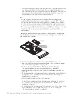
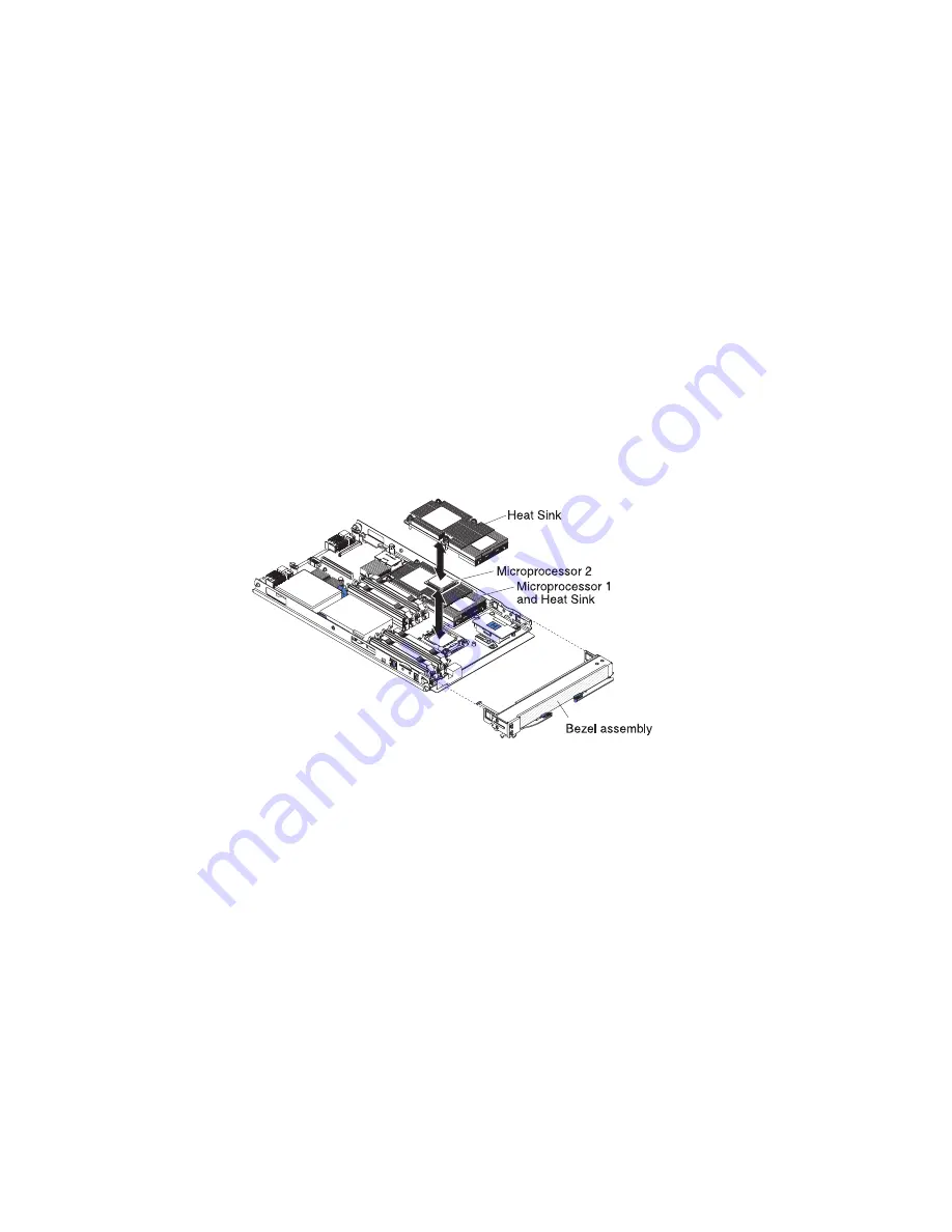
The following illustration shows how to remove a microprocessor and heat sink
from the blade server; the procedure for removing a microprocessor and heat sink
from the MPE unit is similar.
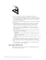
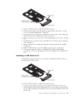
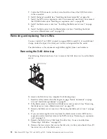
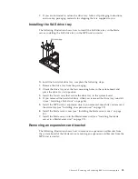
To remove a microprocessor and heat sink, complete the following steps:
1.
Read the safety information that begins on page “Safety statements” on page
viii and “Installation guidelines” on page 25.
2.
If the blade server is installed in a BladeCenter unit, remove it (see
“Removing the blade server from a BladeCenter unit” on page 27).
3.
Remove the blade server cover (see “Removing the blade server cover” on
page 29).
4.
If you are removing a microprocessor from the blade server and an MPE unit
or expansion unit is installed, remove the MPE unit (see “Removing an
expansion unit” on page 31).
5.
Identify the microprocessor that is to be removed.
Note:
If you are replacing a failed microprocessor, make sure that you have
selected the correct microprocessor for replacement (see “System-board
connectors” on page 7).
6.
If you are removing microprocessor 2 (the microprocessor that is closest to the
front of the blade server or MPE unit), remove the bezel assembly (see
“Removing the bezel assembly” on page 33).
58
BladeCenter LS22 Type 7901 and LS42 Type 7902: Problem Determination and Service Guide
Содержание LS42 - BladeCenter - 7902
Страница 1: ...BladeCenter LS22 Type 7901 and LS42 Type 7902 Problem Determination and Service Guide...
Страница 2: ......
Страница 3: ...BladeCenter LS22 Type 7901 and LS42 Type 7902 Problem Determination and Service Guide...
Страница 12: ...x BladeCenter LS22 Type 7901 and LS42 Type 7902 Problem Determination and Service Guide...
Страница 76: ...64 BladeCenter LS22 Type 7901 and LS42 Type 7902 Problem Determination and Service Guide...
Страница 192: ...180 BladeCenter LS22 Type 7901 and LS42 Type 7902 Problem Determination and Service Guide...
Страница 193: ......
Страница 194: ...Part Number 49Y0107 Printed in USA 1P P N 49Y0107...

