v
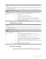
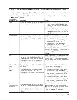
Follow the suggested actions in the order in which they are listed in the Action column until the problem is
solved.
v
See Chapter 3, “Parts listing, Types 7901 and 7902,” on page 19 to determine which components are CRUs and
which components are FRUs.
v
If an action step is preceded by “(Trained service technician only),” that step must be performed only by a
trained service technician.
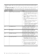
Message
Action
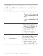
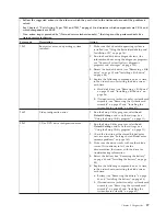
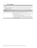
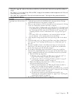
System Power Good fault
1.
Reseat the blade server (see “Removing the blade server from a
BladeCenter unit” on page 27 and “Installing the blade server in a
BladeCenter unit” on page 28).
2.
Check the function of the shared BladeCenter unit resources (see
“Solving shared BladeCenter resource problems” on page 160).
3.
Reseat the MPE unit, if one is installed (see “Removing an
expansion unit” on page 31 and “Installing an expansion unit” on
page 32).
4.
Replace the following components one at a time, in the order
shown, restarting the blade server each time:
a.
(Trained service technician only) MPE board assembly, if one is
installed (see “Removing an expansion unit” on page 31 and
“Installing an expansion unit” on page 32)
b.
(Trained service technician only) System-board assembly (see
“Removing the system-board assembly” on page 62 and
“Installing the system-board assembly” on page 62)
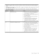
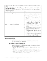
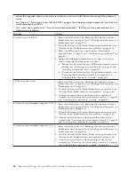
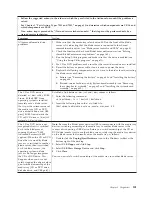
VRM Power Good fault
1.
Reseat the blade server (see “Removing the blade server from a
BladeCenter unit” on page 27 and “Installing the blade server in a
BladeCenter unit” on page 28).
2.
Check the function of the shared BladeCenter unit resources (see
“Solving shared BladeCenter resource problems” on page 160).
3.
(Trained service technician only) Replace the system-board
assembly (see “Removing the system-board assembly” on page 62
and “Installing the system-board assembly” on page 62).
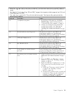
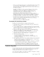
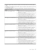
System over recommended voltage for +12v.
1.
Reseat the blade server (see “Removing the blade server from a
BladeCenter unit” on page 27 and “Installing the blade server in a
BladeCenter unit” on page 28).
2.
Check the function of the shared BladeCenter unit resources (see
“Solving shared BladeCenter resource problems” on page 160).
3.
(Trained service technician only) Replace the system-board
assembly (see “Removing the system-board assembly” on page 62
and “Installing the system-board assembly” on page 62).
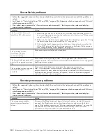
System over recommended voltage for +3.3v.
1.
Reseat the blade server (see “Removing the blade server from a
BladeCenter unit” on page 27 and “Installing the blade server in a
BladeCenter unit” on page 28).
2.
Check the function of the shared BladeCenter unit resources (see
“Solving shared BladeCenter resource problems” on page 160).
3.
(Trained service technician only) Replace the system-board
assembly (see “Removing the system-board assembly” on page 62
and “Installing the system-board assembly” on page 62).
96
BladeCenter LS22 Type 7901 and LS42 Type 7902: Problem Determination and Service Guide
Содержание LS42 - BladeCenter - 7902
Страница 1: ...BladeCenter LS22 Type 7901 and LS42 Type 7902 Problem Determination and Service Guide...
Страница 2: ......
Страница 3: ...BladeCenter LS22 Type 7901 and LS42 Type 7902 Problem Determination and Service Guide...
Страница 12: ...x BladeCenter LS22 Type 7901 and LS42 Type 7902 Problem Determination and Service Guide...
Страница 76: ...64 BladeCenter LS22 Type 7901 and LS42 Type 7902 Problem Determination and Service Guide...
Страница 192: ...180 BladeCenter LS22 Type 7901 and LS42 Type 7902 Problem Determination and Service Guide...
Страница 193: ......
Страница 194: ...Part Number 49Y0107 Printed in USA 1P P N 49Y0107...

