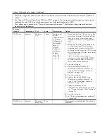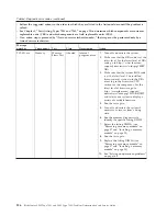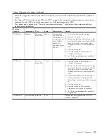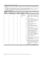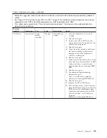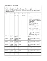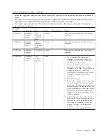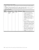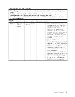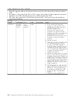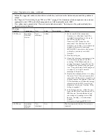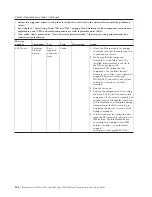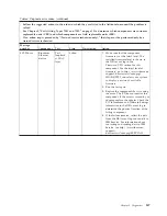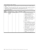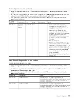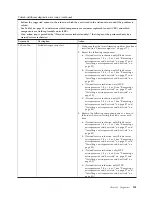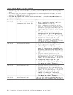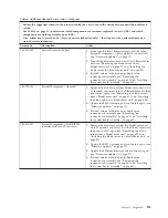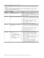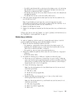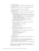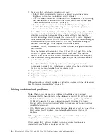
Table 4. Diagnostic error codes (continued)
v
Follow the suggested actions in the order in which they are listed in the Action column until the problem is
solved.
v
See Chapter 3, “Parts listing, Types 7901 and 7902,” on page 19 to determine which components are customer
replaceable units (CRU) and which components are field replaceable units (FRU).
v
If an action step is preceded by “(Trained service technician only),” that step must be performed only by a
trained service technician.
Message
number
Component
Test
State
Description
Action
405-908-xxx
Broadcom
Ethernet
device
Test LEDs
Fail
1.
Make sure that the component
firmware is at the latest level. The
installed firmware level is shown in
the DSA event log in the
Firmware/VPD section for this
component. For the latest level of
firmware, go to http://www.ibm.com/
support/docview.wss?uid=psg1
MIGR-4JTS2T and select your system
to display a matrix of available
firmware.
2.
Run the test again.
3.
Replace the component that is causing
the error. The I/O board contains this
component. If the error is caused by an
adapter, replace the adapter. Check the
PCI Information and Network Settings
information in the DSA event log to
determine the physical location of the
failing component.
4.
See “Solving undetermined problems”
on page 164.
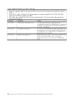
Additional diagnostic error codes
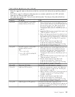
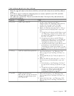
Table 5. Additional diagnostic error codes
v
Follow the suggested actions in the order in which they are listed in the Action column until the problem is
solved.
v
See Table 1 on page 21 to determine which components are customer replaceable units (CRU) and which
components are field replaceable units (FRU).
v
If an action step is preceded by “(Trained service technician only),” that step must be performed only by a
trained service technician.
Error code
Description
Action
001-xxx-001
Failed core tests
(Trained service technician only) Replace the
system-board assembly (see “Removing the system-board
assembly” on page 62 and “Installing the system-board
assembly” on page 62).
005-xxx-000
Failed video test
(Trained service technician only) Replace the
system-board assembly (see “Removing the system-board
assembly” on page 62 and “Installing the system-board
assembly” on page 62).
Chapter 5. Diagnostics
149
Содержание LS42 - BladeCenter - 7902
Страница 1: ...BladeCenter LS22 Type 7901 and LS42 Type 7902 Problem Determination and Service Guide...
Страница 2: ......
Страница 3: ...BladeCenter LS22 Type 7901 and LS42 Type 7902 Problem Determination and Service Guide...
Страница 12: ...x BladeCenter LS22 Type 7901 and LS42 Type 7902 Problem Determination and Service Guide...
Страница 76: ...64 BladeCenter LS22 Type 7901 and LS42 Type 7902 Problem Determination and Service Guide...
Страница 192: ...180 BladeCenter LS22 Type 7901 and LS42 Type 7902 Problem Determination and Service Guide...
Страница 193: ......
Страница 194: ...Part Number 49Y0107 Printed in USA 1P P N 49Y0107...

