Functions
6-45
7SA522 Manual
C53000-G1176-C119-2
6.2.3
Distance Protection with Polygonal Tripping Characteristic
The Distance Protection 7SA522 may optionally be supplied with a polygonal tripping
characteristic or with a circular MHO characteristic, or with both, depending on the ver-
sion ordered. If both characteristics are available, they may be selected for phase–
phase loops and phase–earth loops separately. If only the circular MHO is required,
this Sub-section 6.2.3 is of no interest.
6.2.3.1
Method of Operation
Operating
Polygons
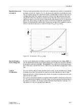
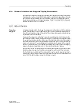
A tripping characteristic in the shape of a polygon is defined for each of the distance
zones. In total, there are five independent zones and one additional controlled zone
for each fault impedance loop. In Figure 6-25 the shape of a polygon is illustrated, us-
ing the first zone as an example.
In general, the polygon is defined by means of a parallelogram which intersects the
axes with the values R and X as well as the tilt
ϕ
Line
. A load trapezoid with the setting
R
Load
und
ϕ
Load
may be used to cut the area of the load impedance out of the polygon.
The axial coordinates can be set individually for each zone;
ϕ
Line
, R
Load
und
ϕ
Load
are
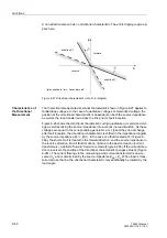
common for all zones. The parallelogram is symmetrical with respect to the origin of
the R–X–coordinate system; the directional characteristic however limits the tripping
range to the desired quadrants (refer to “Direction Determination” below).
The R-reach may be set separately for the phase–phase faults and the phase–earth
faults to achieve a larger fault resistance coverage for earth faults if this is desired.
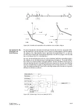
For the first zone an additional tilt
α
exists, which may be used to prevent overreach
resulting from angle variance and/or two ended infeed to short-circuits with fault resist-
ance. For Z1B and the higher zones this tilt does not exist.
Summary of Contents for siprotec 7SA522
Page 20: ...7SA522 Manual C53000 G1176 C119 2 ...
Page 64: ...7SA522 Manual C53000 G1176 C119 2 ...
Page 89: ...SIPROTEC 4 Devices 4 25 7SA522 Manual C53000 G1176 C119 2 Figure 4 20 CFC Logic example ...
Page 408: ...7SA522 Manual C53000 G1176 C119 2 ...
Page 456: ...7SA522 Manual C53000 G1176 C119 2 ...
Page 516: ...7SA522 Manual C53000 G1176 C119 2 ...
Page 620: ...Appendix B 48 ...

