Functions
6-81
7SA522 Manual
C53000-G1176-C119-2
The direct underreach transfer trip application is not provided by its own selectable tel-
eprotection scheme setting, but implemented by setting the teleprotection supplement
to operate in the permissive underreach transfer trip scheme (address
7HOH
SURW'LVW
=
3877
), and using the binary inputs for direct external trip at the re-
ceiving end. Correspondingly, the transmit circuit in Sub-section 6.4.1.1 (Figure 6-45)
applies. For the receive circuit the logic of the “external trip” as described in Section
6.8 applies.
On two terminal lines, the transmission can be phase segregated. On three terminal
lines the transmit signal is sent to both opposite line ends. The receive signals are then
combined with a logical
OR
function.
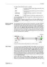
Figure 6-46 Operation scheme of the direct underreach transfer trip method
6.4.1.3
Permissive Overreach Transfer Trip (POTT)
Principle
The permissive overreach transfer mode uses a permissive release principle. The
overreaching zone Z1B set beyond the opposite station is decisive. This mode can
also be used on extremely short lines where a setting of 85 % of line length for zone
Z1 is not possible and accordingly selective non-delayed tripping could not be
achieved. In this case however zone Z1 must be delayed by T1, to avoid non selective
tripping by zone Z1.
Figure 6-47 shows the operation scheme.
If the distance protection recognizes a fault inside the overreaching zone Z1B, it ini-
tially sends a release signal to the opposite line end. If a release signal from the op-
posite line end is received, a trip signal is initiated via the tripping relay. A prerequisite
for fast tripping is therefore that the fault is recognized inside Z1B in the forward direc-
tion at both line ends. The distance protection is set such that the overreaching zone
Z1B reaches beyond the opposite station (approximately 120% of line length). On
three terminal lines, Z1B must be set to reliably reach beyond the longer line section
even with intermediate infeed via the tee point. The first zone is set in accordance with
the normal time grading, i.e. approximately 85 % of the line length, on three terminal
lines, at least beyond the tee point.
T
v
T
v
A
B
Z1(A)
Z1
(A)
T
S
T1
≥
1
Trip
Trans.
Rec.
further
Zones
Z1(B)
Z1
(B)
T
S
T1
≥
1
Trip
Trans.
Rec.
further
Zones
Summary of Contents for siprotec 7SA522
Page 20: ...7SA522 Manual C53000 G1176 C119 2 ...
Page 64: ...7SA522 Manual C53000 G1176 C119 2 ...
Page 89: ...SIPROTEC 4 Devices 4 25 7SA522 Manual C53000 G1176 C119 2 Figure 4 20 CFC Logic example ...
Page 408: ...7SA522 Manual C53000 G1176 C119 2 ...
Page 456: ...7SA522 Manual C53000 G1176 C119 2 ...
Page 516: ...7SA522 Manual C53000 G1176 C119 2 ...
Page 620: ...Appendix B 48 ...


