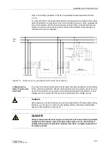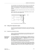
Installation and Commissioning
8-19
7SA522 Manual
C53000-G1176-C119-2
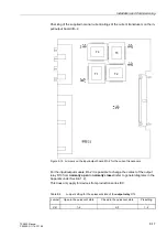
Figure 8-12 Location of the Jumpers for Configuring the Profibus–Interface Terminating
Resistors
To Reassemble
the Device
To reassemble the device, proceed as follows:
o
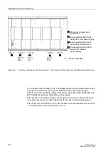
Carefully insert the boards into the case. The installation locations of the boards are
shown in Figure 8-7 and 8-8.
For the model of the device designed for surface mounting, use the metal lever to in-
sert the CPU board. The installation is easier with the lever.
o
First insert the plug connectors on the ribbon cable in the input/output modules I/O and
then on the processor module CPU. Be careful not to bend any of the connecting pins!
Do not use force!
o
Insert the plug connector of the ribbon cable between the processor module CPU and
the front cover in the socket on the front cover.
o
Press the latches of the plug connectors together.
o
Replace the front cover and secure to the housing with the screws.
o
Replace the covers.
o
Re-fasten the interfaces on the rear of the device housing.
This activity is not necessary if the device is for surface mounting.
X3
3
1
2
X4
3
1
2
Jumper
Terminating resistors
Connected
Disconnected
X3
1-2
2-3*
)
X4
1-2
2-3*
)
*
)
Factory Set
C53207-A322-
2 3 4
B100
B101
Summary of Contents for siprotec 7SA522
Page 20: ...7SA522 Manual C53000 G1176 C119 2 ...
Page 64: ...7SA522 Manual C53000 G1176 C119 2 ...
Page 89: ...SIPROTEC 4 Devices 4 25 7SA522 Manual C53000 G1176 C119 2 Figure 4 20 CFC Logic example ...
Page 408: ...7SA522 Manual C53000 G1176 C119 2 ...
Page 456: ...7SA522 Manual C53000 G1176 C119 2 ...
Page 516: ...7SA522 Manual C53000 G1176 C119 2 ...
Page 620: ...Appendix B 48 ...


