Functions
6-37
7SA522 Manual
C53000-G1176-C119-2
During three phase faults the fault detection of all three phase-phase loops usually oc-
curs. In this case the three phase-phase loops are evaluated. If earth fault detection
also occurs, the phase-earth loops are also evaluated.
Correction of meas-
ured values for
Parallel Lines
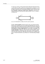
During earth faults on parallel lines, the impedance values calculated by means of the
loop equations are influenced by the coupling of the earth impedance of the two con-
ductor systems (Figure 6-23). Unless special measures are employed, this results in
measuring errors in the result of the impedance computation. A parallel line compen-
sation may therefore be activated. In this manner the earth current of the parallel line
is taken into consideration by the line equation and thereby allows for compensation
of the coupling influence. The earth current of the parallel line must be connected to
the device for this purpose. The loop equation is then modified as shown below, refer
also to Figure 6-21
where
I
EP
is the earth current of the parallel line and the ratio Z
M
/Z
L
is a constant line
parameter, resulting from the geometry of the double circuit line and the nature of the
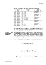
Table 6-2
Evaluation of the measured loops during multiple loop fault detection
Fault detection
Loops
evaluated
Loop(s)
Setting
Parameter
1221
L1–E, L2–E, L1–L2
L2–E, L3–E, L2–L3
L1–E, L3–E, L3–L1
L2–E, L1–L2
L3–E, L2–L3
L1–E, L3–L1
3K(IDXOWV
%ORFNOHDGLQJ
L1–E, L2–E, L1–L2
L2–E, L3–E, L2–L3
L1–E, L3–E, L3–L1
L1–E, L1–L2
L2–E, L2–L3
L3–E, L3–L1
3K(IDXOWV
%ORFNODJJLQJ
L1–E, L2–E, L1–L2
L2–E, L3–E, L2–L3
L1–E, L3–E, L3–L1
L1–E, L2–E, L1–L2
L2–E, L3–E, L2–L3
L1–E, L3–E, L3–L1
3K(IDXOWV
$OOORRSV
L1–E, L2–E, L1–L2
L2–E, L3–E, L2–L3
L1–E, L3–E, L3–L1
L1–L2
L2–L3
L3–L1
3K(IDXOWV
ORRSVRQO\
L1–E, L2–E, L1–L2
L2–E, L3–E, L2–L3
L1–E, L3–E, L3–L1
L1–E, L2–E
L2–E, L3–E
L1–E, L3–E
3K(IDXOWV
(ORRSVRQO\
I
L3
Z
L
I
E
Z
E
I
EP
Z
M
⋅
U
=
L3–E
–
⋅
–
⋅
I
L3
Z
L
I
E
Z
L
Z
E
Z
L
-------
I
EP
Z
L
Z
M
Z
L
-------
⋅
⋅
–
U
L3–E
=
⋅
⋅
–
⋅
Summary of Contents for siprotec 7SA522
Page 20: ...7SA522 Manual C53000 G1176 C119 2 ...
Page 64: ...7SA522 Manual C53000 G1176 C119 2 ...
Page 89: ...SIPROTEC 4 Devices 4 25 7SA522 Manual C53000 G1176 C119 2 Figure 4 20 CFC Logic example ...
Page 408: ...7SA522 Manual C53000 G1176 C119 2 ...
Page 456: ...7SA522 Manual C53000 G1176 C119 2 ...
Page 516: ...7SA522 Manual C53000 G1176 C119 2 ...
Page 620: ...Appendix B 48 ...


