Functions
6-49
7SA522 Manual
C53000-G1176-C119-2
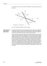
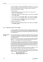
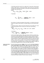
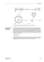
Figure 6-28 Directional characteristic with quadrature or memorized voltages
Assignment to the
Polygons and
Zone Pick-up
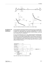
The loop impedances calculated according to Sub-section 6.2.2 are assigned to the
set characteristics of each distance zone. To avoid unstable signals at the boundaries
of a polygon, the characteristics have a hysteresis of approximately 5 % i.e. as soon
as it has been determined that the fault impedance lies within a polygon, the bounda-
ries are increased by 5 % in all directions.
As soon as the fault impedance of any loop is definitely within the operating polygon
of a distance zone, the affected loop is designated as “picked up”. The loop informa-
tion is also converted to phase segregated alarms. Further conditions for pick-up of a
zone are that the direction corresponds to the set direction for the zone, and that the
zone is not blocked by the power swing blocking (refer to Sub-section 6.3.1). Further-
more, the distance protection must not be entirely switched off or blocked. In Figure 6-
29 these conditions are shown.
Figure 6-29 Release logic for a zone (example for Z1)
F
2
F
1
E
1
E
2
Z
S1
Z
S2
Z
L
7SA522
„forward“
„reverse“
R
jX
I
2
I
1
F
1
Z
L
+ Z
S2
„forward“
„reverse“
R
jX
F
2
Z
S1
Z
L
+ Z
S2
6-28a
6-28c
6-28b
Z
S1
Dis switched off
Dis blocked
≥
1
PS blocking
UHYHUVH
IRUZDUG
QRQGLUHFWLRQDO
LQDFWLYH
Dis FD forward
Dis FD reverse
&
&
≥
1
&
2SPRGH=
„1“
&
further
zones
release of Z1
Summary of Contents for siprotec 7SA522
Page 20: ...7SA522 Manual C53000 G1176 C119 2 ...
Page 64: ...7SA522 Manual C53000 G1176 C119 2 ...
Page 89: ...SIPROTEC 4 Devices 4 25 7SA522 Manual C53000 G1176 C119 2 Figure 4 20 CFC Logic example ...
Page 408: ...7SA522 Manual C53000 G1176 C119 2 ...
Page 456: ...7SA522 Manual C53000 G1176 C119 2 ...
Page 516: ...7SA522 Manual C53000 G1176 C119 2 ...
Page 620: ...Appendix B 48 ...


