Installation and Commissioning
8-32
7SA522 Manual
C53000-G1176-C119-2
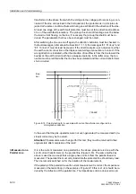
The configuration shown in Figure 8-17 corresponds to an earth current flowing
through the line, in other words an earth fault in the forward direction.
At least one stage of the earth fault protection must be set to be directional (address
[[
of the earth fault protection). The test current on the line must exceed the pick-
up threshold setting of this/these stages; if required, the pick-up threshold setting must
be reduced. The parameters that are changed, must be noted.
Figure 8-17
Polarity check of I
4
, example with earth current from a power transformer star-point
After switching the test source on and off again, the direction indication must be
checked: In the fault messages (refer also to Sub-section 7.1.1.3) at least the following
alarms must be present “
” and “
”. If the directional pick-up
alarm is missing, a connection error of the earth current connection I
4
is present. If the
wrong direction is indicated, the earth current connection I
4
has a swapped polarity.
The connection must be rectified after the test source has been switched off. The
measurement must then be repeated.
If the pick-up alarm is missing altogether, this may be due to the fact that the test cur-
rent is too small.
Attention! If parameters were changed for this test, they must be returned to their
original state after completion of the test!
8.3.5
Measuring the operating time of the circuit breaker
Only for synchro-
nism check
If the device is equipped with the function for synchronism and voltage check and it is
applied, it is necessary - under asynchronous system conditions - that the operating
time of the circuit breaker is measured and set correctly when closing. If the synchro-
nism check function is not used or only for closing under synchronous system condi-
tions, this subsection is irrelevant.
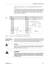
For measuring the operating time a setup as shown in figure 8-18 is recommended.
The timer is set to 1 s and a graduation of 1 ms.
Bus-
bar
Line
A
B
C
6$
I
L1
I
L3
I
L2
I
4
’
Transformer
I
L1
’
I
L3
’
I
L3
’
I
4
Test source
Summary of Contents for siprotec 7SA522
Page 20: ...7SA522 Manual C53000 G1176 C119 2 ...
Page 64: ...7SA522 Manual C53000 G1176 C119 2 ...
Page 89: ...SIPROTEC 4 Devices 4 25 7SA522 Manual C53000 G1176 C119 2 Figure 4 20 CFC Logic example ...
Page 408: ...7SA522 Manual C53000 G1176 C119 2 ...
Page 456: ...7SA522 Manual C53000 G1176 C119 2 ...
Page 516: ...7SA522 Manual C53000 G1176 C119 2 ...
Page 620: ...Appendix B 48 ...


