Functions
6-249
7SA522 Manual
C53000-G1176-C119-2
6.18.3 Data Storage for Fault Recording
The Distance Protection 7SA522 has a fault recording memory. The instantaneous
values of the measured signals
i
L1
, i
L2
, i
L3
, i
E
or i
EE
and u
L1
, u
L2
, u
L3
, u
en
(voltages according to type of connection) are sampled at an interval of 1 ms (at
50 Hz) respectively 0.83 ms (at 60 Hz), and stored in a circular shift register (20 sam-
ples per cycle). In the event of a fault the data is memorized for a selectable period of
time. Up to 8 fault recordings can be memorized. The recording memory is automati-
cally updated in the event of a new system fault, thereby not requiring an acknowledg-
ment. In addition to storage of the fault recording by the protection fault detection this
may also be initiated via binary input, the integrated keypad and display, or via the se-
rial PC or service interface.
The data can be retrieved via the serial interfaces by means of a personal computer
and evaluated with the protection data processing program DIGSI
®
4 and the graphic
analysis software DIGRA
®
4. The latter graphically represents the data recorded dur-
ing the system fault and calculates additional information such as the impedance or
RMS values from the measured values. A selection may be made as to whether the
currents and voltages are represented as primary or secondary values. Binary signal
traces (marks) of particular events e.g. “fault detection”, “tripping” are also represent-
ed.
If the device has a serial system interface, the disturbance recording data can be
passed on to a central device via this interface. The evaluation of the data is done by
applicable programs in the central device. Currents and voltages are referred to their
maximum values, scaled to their rated values and prepared for graphic representation.
In addition, internal events are recorded as binary traces (marks), e.g. “fault detec-
tion”, “tripping”.
In the event of transfer to a central device, the request for data transfer can be exe-
cuted automatically and can be selected to take place after each fault detection by the
protection, or only after a trip.
6.18.4 Applying the Function Parameter Settings
Data Storage for
Fault Recording
The configuration of the fault recording memory is done in the sub-menu
2VFLOOR
JUDSKLF)DXOW5HFRUGLQJV
of the menu
6HWWLQJV
. A distinction is made be-
tween the reference instant and the storage criterion of the fault recording (address
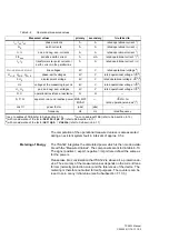
Table 6-10
Operational Metering Impulse Counters
Measured Values
primary
W
p
+
active power, export
kWh, MWh, GWh
W
p
–
active power, import
kWh, MWh, GWh
W
q
+
reactive power, export
kVARh, MVARh, GVARh
W
q
–
reactive power, import
kVARh, MVARh, GVARh
Summary of Contents for siprotec 7SA522
Page 20: ...7SA522 Manual C53000 G1176 C119 2 ...
Page 64: ...7SA522 Manual C53000 G1176 C119 2 ...
Page 89: ...SIPROTEC 4 Devices 4 25 7SA522 Manual C53000 G1176 C119 2 Figure 4 20 CFC Logic example ...
Page 408: ...7SA522 Manual C53000 G1176 C119 2 ...
Page 456: ...7SA522 Manual C53000 G1176 C119 2 ...
Page 516: ...7SA522 Manual C53000 G1176 C119 2 ...
Page 620: ...Appendix B 48 ...


