Appendix
A-9
7SA522 Manual
C53000-G1176-C119-2
1.2.2
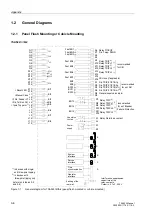
Panel Surface Mounting
7SA522
∗
−
∗
E
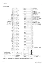
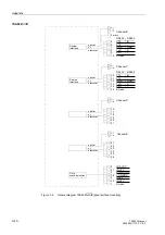
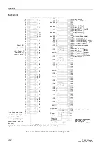
Figure 1-4
General diagram 7SA522
∗
–
∗
E (panel surface mounting)
For connections of the further interfaces see Figure 1-5.
Power
Earthing at the
supply
side wall
25
50
I
L1
22
47
I
4
24
49
I
L2
23
48
I
L3
21
46
U
4
20
19
U
L1
45
43
18
BI1
U
L2
41
40
BI3
14
39
BI4
BI5
L+
L–
( )
~
+
-
74
99
BO8
73
BO9
97
BO10
86
61
Fast BO4
85
60
Fast BO5
44
U
L3
42
17
BI2
38
13
BI6
37
12
BI7
36
11
BI8
63
87
62
Fast BO2
88
Fast BO3
Fast BO1
84
59
Fast BO6
83
58
Fast BO7
98
72
BO12
BO11
96
71
BO13
95
70
BO14
94
69
BO15
Operator
interface
Live status
90
65
contact
1 2
3 2
>Reset LED
>Manual Close
>FAIL: Feeder VT
>Dis.Tel.Rec.Ch1
>1poleTrip perm.
1)
1)
in devices with single-
2)
in devices with
(refer also to tables 5-5
and three-pole tripping
three-pole tripping only
and 5-6)
Relay PICKUP
Dis. Telep. SEND
Relay TRIP
2)
Relay TRIP L1
1)
Relay TRIP L2
1)
Relay TRIP
2)
Relay TRIP L3
1)
recom.
for CB
Dis. TRIP Z1/Z1B, 1p
Dis. TRIP Z1/Z1B, 3p
Dis. TRIP Z1/Z1B, sf
2)
Dis. TRIP Z1/Z1B, mf
2)
General supervision alarm
Relay TRIP
2)
Relay TRIP L1
1)
Relay TRIP L2
1)
Relay TRIP
2)
Relay TRIP L3
1)
recom.
for ext.
Failure
recom.
for ext.
AR
Breaker
Protection
Relay Alarm/Live contact
Interference suppression
capacitors at the
Ceramic, 4.7 nF, 250 V
relay contacts,
1 2
3 2
AR close (if applicable)
Summary of Contents for siprotec 7SA522
Page 20: ...7SA522 Manual C53000 G1176 C119 2 ...
Page 64: ...7SA522 Manual C53000 G1176 C119 2 ...
Page 89: ...SIPROTEC 4 Devices 4 25 7SA522 Manual C53000 G1176 C119 2 Figure 4 20 CFC Logic example ...
Page 408: ...7SA522 Manual C53000 G1176 C119 2 ...
Page 456: ...7SA522 Manual C53000 G1176 C119 2 ...
Page 516: ...7SA522 Manual C53000 G1176 C119 2 ...
Page 620: ...Appendix B 48 ...

