Configuration
5-3
7SA522 Manual
C53000-G1176-C119-2
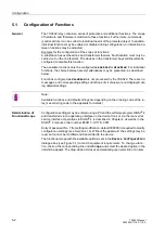
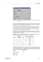
Figure 5-1
Device Configuration dialogue box in DIGSI
®
4 — example
Before closing the dialogue box, transfer the modified functional setting to the relay by
clicking on the item
',*6,
→
'HYLFH
. The data is stored in the relay in a non-volatile
memory buffer.
The configured functional scope can be
viewed
at the front of the relay itself, but can-
not be modified there. The settings associated with the functional scope can be found
in the
0$,10(18
under
→
6HWWLQJV
→
'HYLFH&RQILJ
.
Special Cases
Most settings are self-explanatory. The special cases are described below.
If the setting group change-over function is to be used, the setting in address
*US&KJH237,21
must be set to
(QDEOHG
. In this case, it is possible to apply up to
four different groups of settings for the function parameters (refer also to Sub-section
6.1.2). During normal operation, a convenient and fast switch-over between these set-
ting groups is possible. The setting
'LVDEOHG
implies that only one function parame-
ter setting group can be applied and used.
The tripping characteristic type can be selected for the distance protection, dependent
on the device version. In setting address
the selection for the phase–phase
measuring systems
3KDVH'LVWDQFH
is done and in address
the selection for
the phase–earth measuring systems
(DUWK'LVWDQFH
is done. A selection between
a polygonal tripping characteristic
4XDGULODWHUDO
and circular MHO characteristic
0+2
is available. In Sub-sections 6.2.3 and 6.2.4 the characteristics and measuring
techniques are described in detail. The setting in these two addresses may be differ-
ent. If the device is to be applied for only phase–earth loops or only phase–phase
loops, then the unused function is set to
'LVDEOHG
.
If the distance protection is to be supplemented with a teleprotection system, the de-
sired scheme can be selected in address
7HOHSURW'LVW
. A selection be-
tween the permissive underreach transfer scheme
3877
, the permissive overreach
transfer scheme
3277
, the
81%/2&.,1*
scheme, and a
%/2&.,1*
scheme are avail-
able. These schemes are described in detail in Sub-section 6.4.1. If a teleprotection
supplement is not required for the distance protection, the setting must be
'LVDEOHG
.
The tripping characteristic of the time delayed overcurrent protection can be set in ad-
dress
. In addition to the definite time
Summary of Contents for siprotec 7SA522
Page 20: ...7SA522 Manual C53000 G1176 C119 2 ...
Page 64: ...7SA522 Manual C53000 G1176 C119 2 ...
Page 89: ...SIPROTEC 4 Devices 4 25 7SA522 Manual C53000 G1176 C119 2 Figure 4 20 CFC Logic example ...
Page 408: ...7SA522 Manual C53000 G1176 C119 2 ...
Page 456: ...7SA522 Manual C53000 G1176 C119 2 ...
Page 516: ...7SA522 Manual C53000 G1176 C119 2 ...
Page 620: ...Appendix B 48 ...


