Technical Data
10-11
7SA522 Manual
C53000-G1176-C119-2
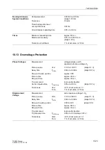
Mutual Impedance
Matching
(for Parallel Lines)
R
M
/R
L
0.00 to 8.00
(steps 0.01)
X
M
/X
L
0.00 to 8.00
(steps 0.01)
The matching factors for earth impedance and mutual impedance are valid also for
fault location.
Phase Preferences
for double earth fault
lagging phase–earth and phase–phase
in earthed systems
leading phase–earth and phase–phase
all associated loops
only phase-to-earth loops
only phase-to-phase loop
Earth Fault
Detection
Earth current 3I
0
>
0.05· A to 4.00·A
*)
(steps 0.01·A)
Displacement voltage 3U
0
>
1 V to 100 V;
∞
(steps 1 V)
Drop-out to pick-up ratios
approx. 0.95
Measuring tolerances
± 5 %
*) Secondary values based on I
N
= 1 A; for I
N
= 5 A they must be multiplied with 5.
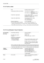
Distance
Measurement
Characteristic
polygonal or MHO–circle
(depending on ordered version);
5 independent and 1 controlled zone
Setting ranges polygon:
I
Ph
> = min. current, phases
0.10· A to 4.00·A
1)
(steps 0.01·A)
X
= reactance reach
0.05
Ω
to 250.00
Ω
2)
(steps 0.01
Ω
)
R
= resistance tolerance phase–phase0.05
Ω
to 250.00
Ω
2)
(steps 0.01
Ω
)
RE = resistance tolerance phase–earth 0.05
Ω
to 250.00
Ω
2)
(steps 0.01
Ω
)
ϕ
Line
= line angle
30° to 89°
(steps 1°)
α
Pol
= tilt angle for 1st zone
0° to 30°
(steps 1°)
Direction determination for polygonal characteristic:
for all types of fault
with phase-true, memorized,
or quadrature voltages
directional sensitivity
dynamically unlimited,
approx. 1 V under steady-state operation
All zones can be set to operate in forward or reverse direction, non-directional or
ineffective.
Setting ranges MHO–circle:
I
Ph
> = min. current, phases
0.10· A to 4.00·A
1)
(steps 0.01·A)
Z
r
= impedance reach
0.05
Ω
to 200.00
Ω
2)
(steps 0.01
Ω
)
Polarization
with memorized or
quadrature voltages
All zones can be set to operate in forward or reverse direction or ineffective.
Load trapezoid:
R
load
= minimum load resistance
0.10
Ω
to 250.00
Ω
2)
;
∞
(steps 0.01
Ω
)
ϕ
load
= maximum load angle
20° to 60°
(steps 1°)
Drop-out to pick-up ratios
approx. 1.06
Measured value correction
mutual impedance matching for parallel
lines (ordering option)
Summary of Contents for siprotec 7SA522
Page 20: ...7SA522 Manual C53000 G1176 C119 2 ...
Page 64: ...7SA522 Manual C53000 G1176 C119 2 ...
Page 89: ...SIPROTEC 4 Devices 4 25 7SA522 Manual C53000 G1176 C119 2 Figure 4 20 CFC Logic example ...
Page 408: ...7SA522 Manual C53000 G1176 C119 2 ...
Page 456: ...7SA522 Manual C53000 G1176 C119 2 ...
Page 516: ...7SA522 Manual C53000 G1176 C119 2 ...
Page 620: ...Appendix B 48 ...


