Installation and Commissioning
8-13
7SA522 Manual
C53000-G1176-C119-2
o
At one end, disconnect the ribbon-cable between the front cover and the CPU board
(
å
). To disconnect the cable, push up the top latch of the plug connector and push
down the bottom latch of the plug connector. Carefully set aside the front cover.
o
Disconnect the ribbon-cables between the CPU board (
å
) and the I/O boards (
ê
).
o
Remove the boards and set them on the grounded mat to protect them from ESD dam-
age. A greater effort is required to withdraw the CPU board, especially in versions of
the device for surface-mounting, because of the communication connectors.
o
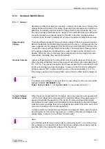
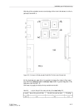
Check the jumpers according to Figures 8-9 to 8-12. Change or remove the jumpers
as necessary.
o
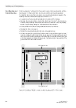
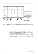
The order of the boards for housing size
1
/
2
is shown in figure 8-7,
for housing size
1
/
1
refer to figure 8-8.
Figure 8-7 Front view of the device with housing size
1
/
2
after removal of the front cover (sim-
plified and scaled down)
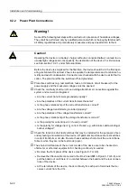
Caution!
Electrostatic discharges through the connections of the components, wiring, plugs,
and jumpers must be avoided. Wearing a grounded wrist strap is preferred. Otherwise,
first touch a grounded metal part.
1
2
3
Slot 5
Slot 19
Slot 33
Binary inputs (BI)
BI1 to
Input/output printed circuit board I/O-1
Input/output printed circuit board I/O-2
Prozessorbaugruppe
Processor printed circuit board CPU
1
2
3
BI8
(transducers)
with power supply
Summary of Contents for siprotec 7SA522
Page 20: ...7SA522 Manual C53000 G1176 C119 2 ...
Page 64: ...7SA522 Manual C53000 G1176 C119 2 ...
Page 89: ...SIPROTEC 4 Devices 4 25 7SA522 Manual C53000 G1176 C119 2 Figure 4 20 CFC Logic example ...
Page 408: ...7SA522 Manual C53000 G1176 C119 2 ...
Page 456: ...7SA522 Manual C53000 G1176 C119 2 ...
Page 516: ...7SA522 Manual C53000 G1176 C119 2 ...
Page 620: ...Appendix B 48 ...

