Cycle time
The analog/digital conversion and the transfer of the digitized measured values to memory or
to the backplane bus take place sequentially. In other words, the analog input channels are
converted one after the other. The cycle time, that is, the time until an analog output value is
converted again, is the sum of the conversion times of all the activated analog output channels
of the analog input modules. You should deactivate unused analog input channels during
parameter assignment in order to reduce the cycle time. The conversion and integration time
for a deactivated channel is 0.
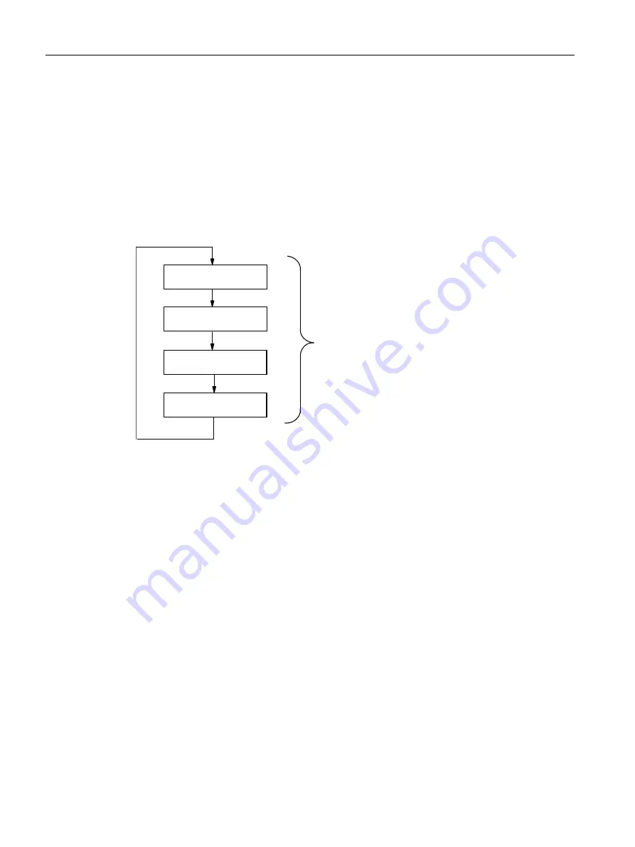
The following figure provides you with an overview of what makes up the cycle time for an n-
channel analog input module.
&RQYHUVLRQWLPH
FKDQQHO
&\FOHWLPH
&RQYHUVLRQWLPH
FKDQQHO
&RQYHUVLRQWLPH
FKDQQHO
&RQYHUVLRQWLPH
FKDQQHO
Figure A-7
Cycle time of the analog input module
A.3.7
Reaction times for analog output modules
Conversion time
The conversion time of the analog output channels includes the transfer of digitized output
values from internal memory, and their digital-to-analog conversion.
Cycle time
The conversion of the analog output channels for the module takes place with a processing
time and sequentially with a conversion time for channels 0,1, 2 and 3.
The cycle time, that is, the time until an analog output value is converted again, is the sum of
the conversion times of all the activated analog output channels and of the processing time of
the analog output module.
The following figure provides you with an overview of what makes up the cycle time for an
analog output module.
Appendix
A.3 Reaction times
ET 200iSP
346
Operating Instructions, 11/2017, A5E00247483-07


