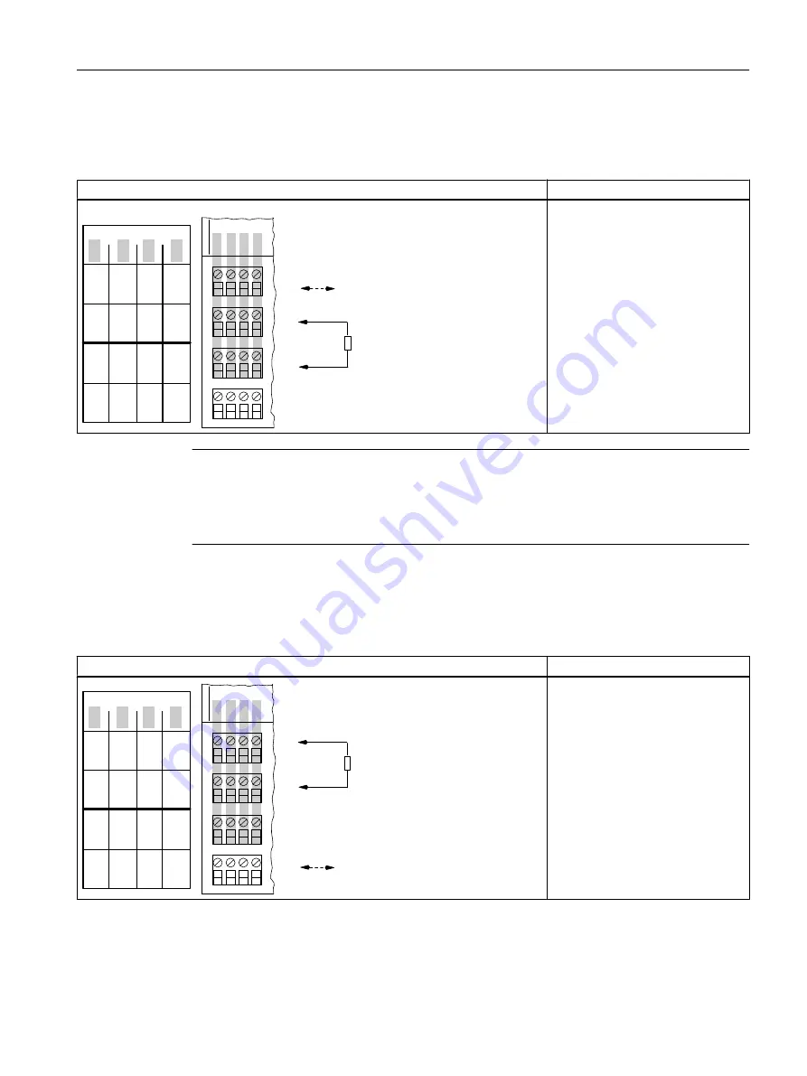
Pin assignment for enhanced performance (only for 4 DO DC17.4V/27mA, 4 DO DC17.4V/40mA)
Table 12-9
Pin assignment for enhanced performance
Pin assignment and view
Remarks
'2
'2
'2
'2
'2
'2
0
0 0
0
6,
6,
0
6,
6,
0
&KDQQHO
&RQQHFWLRQH[DPSOHIRU
SHUIRUPDQFHHQKDQFHPHQW
WKRXJKSDUDOOHOVZLWFKLQJRI
FKDQQHODQGFKDQQHO
HJDFWXDWRURQ
FKDQQHO
-XPSHUIRU
HQKDQFHG
SHUIRUPDQFH
Increased power:
Parallel wiring of channel 0 and
channel 1: Jumper from 1 to 5; ac‐
tuator at 2 and 3
Parallel wiring of channel 2 and
channel 3 Jumper from 9 to 13; ac‐
tuator at 10 and 11
DO: Digital outputs
M: Chassis ground
Note
If the actuator disconnection signal is wired in parallel via terminals 4/8 and 12/16, note this
connection will be interrupted when a 4DO module is removed. If hot swapping is intended
when the actuator disconnection is activated, the individual modules must be connected
directly to the signal source.
Pin assignment for actuator disconnection
Table 12-10 Pin assignment for actuator disconnection
Pin assignment and view
Remarks
'2
'2
'2
'2
'2
'2
0
0 0
0
6,
6,
0
6,
6,
0
&KDQQHO
&RQQHFWLRQH[DPSOHIRU
DFWXDWRUGLVFRQQHFWLRQ
HJDFWXDWRU
RQFKDQQHO
,QSXWIRUDFWXDWRU
GLVFRQQHFWLRQ
Actuator deactivation of all outputs
channel 0 to channel 3:
Terminal 4/8: High active (intrinsi‐
cally safe) or low active signal (see
Figure "Actuator disconnection via
intrinsically safe shutdown signal for
SHUT DOWN "H" output modules")
Terminal 12/16: Chassis ground
DO: Digital outputs
M: Chassis ground
SI
+
: Signal input for actuator discon‐
nection
SI
M
: Chassis ground
Digital electronic modules
12.2 Digital electronics module 4 DO
ET 200iSP
Operating Instructions, 11/2017, A5E00247483-07
245


