3.3.11
Movimentazione testata
tranciarami
PERICOLO
Prima di sollevare l’accessorio inserire
le apposite bandelle di sicurezza sugli
utensili da taglio.
Il peso dell’accessorio è stampato sulla
targhetta CE.
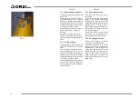
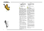
Per movimentare l’accessorio sollevare
l’attrezzo mediante catena inserendo i
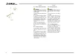
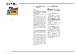
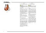
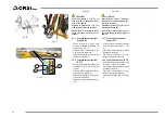
ganci o cavallotti (2, “Fig. 25”) nei 2 fori
presenti sulle estremità specificati da pitto
-
gramma (1, “Fig. 25”). Sollevare con cau-
tela. Controllare la stabilità del carico. Sol-
levare l’accessorio con estrema cautela
e trasferirla lentamente, senza movimenti
bruschi, sull’autocarro o sul vagone
ferroviario.
Il pianale su cui si intende caricare la
macchina, deve essere perfettamente in
piano per evitare possibili spostamenti del
carico.
3.3.12 Scarico testata tranciarami
La massa della macchina è stampato sulla
targhetta CE, utilizzare un mezzo di ade-
guato.
Per movimentare l’accessorio sollevare
l’attrezzo mediante catena inserendo i
ganci o cavallotti (2, “Fig. 25”) nei 2 fori
presenti sulle estremità specificati da pitto
-
gramma (1, “Fig. 25”). Sollevare con cau-
tela. Controllare la stabilità del carico. Sol-
levare l’accessorio con estrema cautela
e trasferirla lentamente, senza movimenti
bruschi, a terra. Il suolo deve risultare per-
fettamente piano per evitare il ribaltamen-
to della macchina.
3.3.11
Handling branch cutter
DANGER
Before lifting the accessory insert the
appropriate safety strips on cutting to-
ols.
The weight of the accessory is printed on
the CE plate.
To move the accessory lift the tool through
a chain inserting the hooks or holders (2,
“Fig 25”) in the 2 holes on the ends speci-
fied by the pictogram (1, “Fig 25”). Care
-
fully lift. Check the stability of the load. Lift
the tool with extreme caution and transfer
it slowly, without sudden movements, onto
the truck or railcar.
The platform on which you want to load
the machine, must be perfectly level to
prevent possible movement of the load
3.3.12
Unloading branch cutter
The mass of the equipment is printed on
the CE plate, use a suitable means.
To move the accessory lift the tool through
a chain inserting the hooks or holders (2,
“Fig 25”) in the 2 holes on the ends spe-
cified by the pictogram (1, “Fig 25”). Ca
-
refully lift. Check the stability of the load.
Lift the tool with extreme caution and tran-
sfer it slowly, without sudden movements,
ground. The soil must be perfectly plane to
avoid tipping machine.
74
ITALIANO
ENGLISH
1
2
Fig. 25
Summary of Contents for Acrobat 4.4
Page 5: ...River Compact 355 River Compact 420 Royal 550 Royal 660 Royal 650 T Royal 760 T Vigna 615 T 5...
Page 45: ...45 DEUTSCH ESPA OL FRAN AIS ITALIANO ENGLISH...
Page 57: ...57 DEUTSCH ESPA OL FRAN AIS ITALIANO ENGLISH...
Page 227: ...227...
Page 256: ...256...
Page 257: ...257...

