4.2.4. Using the user interface
4.2.4.1. Drive screen
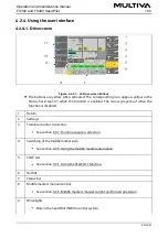
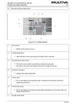
Figure. 4.2.4.1. - 42. Drive screen buttons
The buttons are yellow when activated. The corresponding icon appears yellow in the
Status bar screen (7) when the function is enabled. The icon is greyed out when the
function is disabled.
1.
Return
2.
Settings
3.
Tramline counter correction
See section 6.3.7. Tramline counter correction.
4.
Switching of the middle marker side
See section 6.3.5. Using the middle marker automation.
5.
STOP ALL
See section 6.3.1. Using the STOP ALL function.
6.
Half lift
7.
Status bar
8.
Middle markers manual control
See section 6.3.6. Middle markers manual control and forcing operation.
9.
Work lights
Only in the SeedPilot ISOBUS control system.
Operation and maintenance manual
FX300 and FX400 SeedPilot
1.00
44 (208)
Summary of Contents for FX300 SeedPilot
Page 200: ...Hydraulic schematics FX300 and FX400 1 Hydraulic schematics FX300...
Page 201: ...Hydraulic schematics FX300 and FX400 2...
Page 202: ...Hydraulic schematics FX300 and FX400 3 Hydraulic schematics FX400...
Page 203: ...Hydraulic schematics FX300 and FX400 4...
Page 204: ...Electrical schematics FX300 and FX400 1 Electrical schematics...

