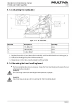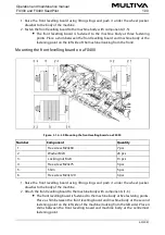
1. Connect the 5-metre connecting cable (3) to the 1-metre cable (1) with connector M12
(2).
The 5-metre connecting cable will be connected to the tractor cabin. Fasten the
cable properly so that it is not pinched during turns or lifting.
Figure. 5.2.1. - 73. Fastening of the area counter
2. Fasten the display counterpart (4) to the metal plate (3) with two fastening screws (5).
3. Attach the metal plate to the cabin from the fastening holes (2) by two fastening screws
Attach the display in a location where view is not obstructed but where the
display is easily viewable by turning one's glance while driving. Ensure that the
cable is sufficiently long to reach the display fastening spot.
4. Snap the area counter display (1) to the metal plate.
5.2.2. Installing the SeedPilot control panel
Figure. 5.2.2. - 74. Installing the SeedPilot control panel
1. Push the control panel wiring harness through the hole in the mounting adapter (2).
Operation and maintenance manual
1.00
FX300 and FX400 SeedPilot
71 (208)
Summary of Contents for FX300 SeedPilot
Page 200: ...Hydraulic schematics FX300 and FX400 1 Hydraulic schematics FX300...
Page 201: ...Hydraulic schematics FX300 and FX400 2...
Page 202: ...Hydraulic schematics FX300 and FX400 3 Hydraulic schematics FX400...
Page 203: ...Hydraulic schematics FX300 and FX400 4...
Page 204: ...Electrical schematics FX300 and FX400 1 Electrical schematics...


