4.2.1.3. Speed sensor
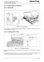
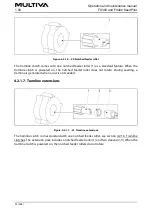
Figure. 4.2.1.3. - 16. Speed sensor
The speed sensor (1) is an inductive sensor, which measures the seed drill speed and seeded
area. The controller display shows the driving speed and the seeded area.
4.2.1.4. Shaft rotation guards
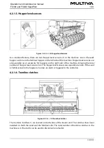
Figure. 4.2.1.4. - 17. Shaft rotation guards
There are 2 shaft rotation guards. An inductive sensor (1, 4) and sensor wheel (2, 3) are located
on the left edge of the feeder unit on both the fertiliser and seed sides (viewed from the back of
the machine). The sensor wheel has 12 key steel rods. The rotation monitors ensure that the
feeder shaft is rotating and the feeder units are feeding seed and fertiliser. If the feeder shaft is
not rotating, an alarm is triggered in the control system.
Operation and maintenance manual
1.00
FX300 and FX400 SeedPilot
31 (208)
Summary of Contents for FX300 SeedPilot
Page 200: ...Hydraulic schematics FX300 and FX400 1 Hydraulic schematics FX300...
Page 201: ...Hydraulic schematics FX300 and FX400 2...
Page 202: ...Hydraulic schematics FX300 and FX400 3 Hydraulic schematics FX400...
Page 203: ...Hydraulic schematics FX300 and FX400 4...
Page 204: ...Electrical schematics FX300 and FX400 1 Electrical schematics...

