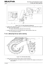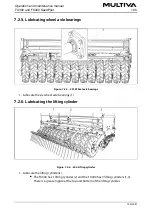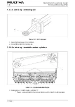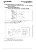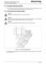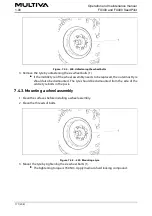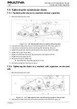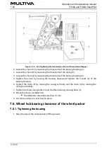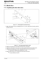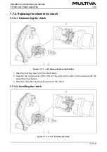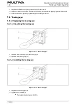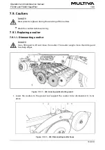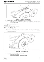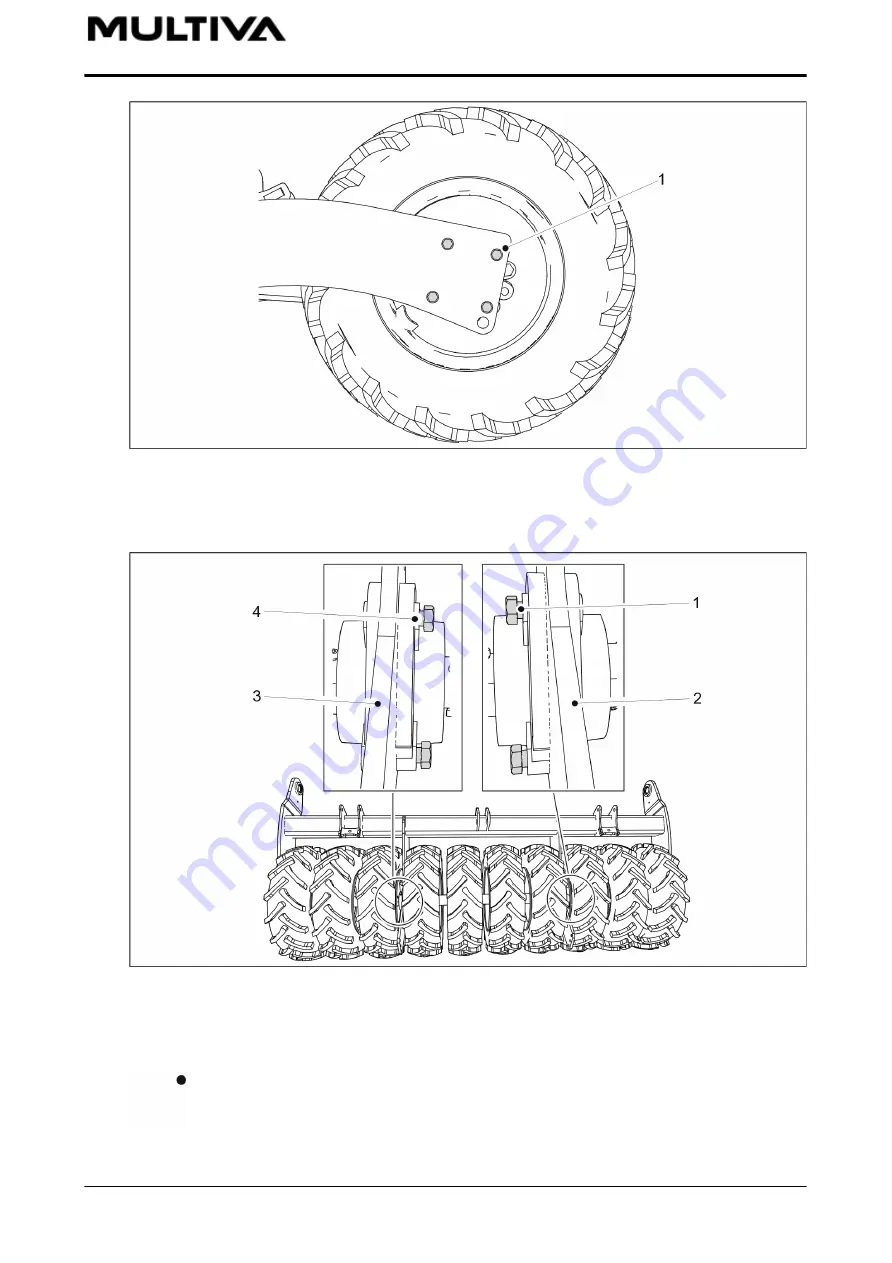
Figure. 7.4.1. - 224. Dismounting the wheel assembly
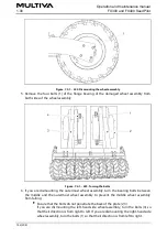
5. Remove the four bolts (1) of the ange bearing of the damaged wheel assembly from
both sides of the wheel assembly.
Figure. 7.4.1. - 225. Turning the bolts
6. If you are dismounting the outermost wheel assembly, turn the bearing bolts between
the middle and the outermost wheel assembly to prevent the middle wheel assembly
from falling.
Ensure that the bolts do not penetrate the back of the plate (2, 3).
If you are dismounting the left-hand side wheel assembly, turn the bolts (4) so
that their direction is from right to left. If you are dismounting the right-hand side
wheel assembly, turn the bolts (1) so that their direction is from left to right.
Operation and maintenance manual
1.00
FX300 and FX400 SeedPilot
169 (208)
Summary of Contents for FX300 SeedPilot
Page 200: ...Hydraulic schematics FX300 and FX400 1 Hydraulic schematics FX300...
Page 201: ...Hydraulic schematics FX300 and FX400 2...
Page 202: ...Hydraulic schematics FX300 and FX400 3 Hydraulic schematics FX400...
Page 203: ...Hydraulic schematics FX300 and FX400 4...
Page 204: ...Electrical schematics FX300 and FX400 1 Electrical schematics...

