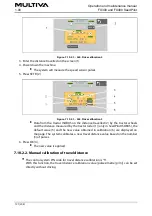
Figure. 7.10.2.1. - 264. Drive calibration 2
3. Enter the distance travelled on the screen (1).
4. Power down the machine.
The system will measure the speed sensor pulses.
5. Press SET B (2).
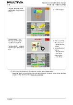
Figure. 7.10.2.1. - 265. Drive calibration 3
Data from the tractor ISOBUS on the distance travelled (2) by the tractor wheels
and the distance measured by the tractor radar (1) (only in SeedPilot ISOBUS), the
default value (5) and the new value obtained in calibration (6) are displayed on
the page. The system calibrates a new travel distance value based on the number
(3) of pulses.
6. Press OK (4).
The new value is applied.
7.10.2.2. Manual calibration of travel distance
The control system PIN code for travel distance calibration is “5”.
With this function, the travel distance calibration value (pulses/metre [p/m]) can be set
directly without driving.
Operation and maintenance manual
1.00
FX300 and FX400 SeedPilot
191 (208)
Summary of Contents for FX300 SeedPilot
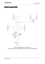
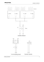
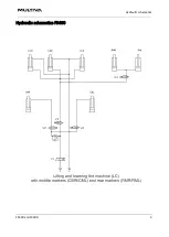
Page 200: ...Hydraulic schematics FX300 and FX400 1 Hydraulic schematics FX300...
Page 201: ...Hydraulic schematics FX300 and FX400 2...
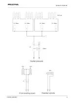
Page 202: ...Hydraulic schematics FX300 and FX400 3 Hydraulic schematics FX400...
Page 203: ...Hydraulic schematics FX300 and FX400 4...
Page 204: ...Electrical schematics FX300 and FX400 1 Electrical schematics...

