4.2.1. Control system components
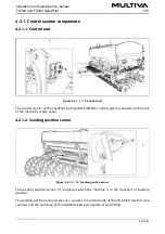
4.2.1.1. Control unit
Figure. 4.2.1.1. - 14. Control unit
The control unit (1) of the SeedPilot and SeedPilot ISOBUS control system is located on the front
of the machine’s centre panel.
4.2.1.2. Seeding position sensor
Figure. 4.2.1.2. - 15. Seeding position sensor
The seeding position sensor (1) recognises when the machine is in the transport or seeding
position.
The seeding position sensor works as a counter. In normal mode of the lift inhibit function, the
counters and the switching of the middle marker side operate at each lifting.
Operation and maintenance manual
FX300 and FX400 SeedPilot
1.00
30 (208)
Summary of Contents for FX300 SeedPilot
Page 200: ...Hydraulic schematics FX300 and FX400 1 Hydraulic schematics FX300...
Page 201: ...Hydraulic schematics FX300 and FX400 2...
Page 202: ...Hydraulic schematics FX300 and FX400 3 Hydraulic schematics FX400...
Page 203: ...Hydraulic schematics FX300 and FX400 4...
Page 204: ...Electrical schematics FX300 and FX400 1 Electrical schematics...


