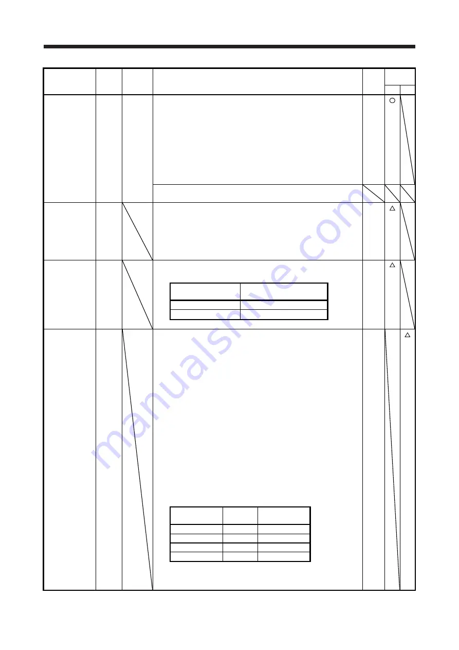
12. WHEN USING WITH A GENERAL-PURPOSE INTERFACE
12 - 11
Device
Symbol
Connector
pin No.
Function and application
I/O
division
Control
mode
CP PS
Reverse rotation
start
ST2
CN3-4
Point table method
Use this device with the incremental value command method. When ST2 is
turned on during automatic operation, positioning is executed once in the
reverse rotation in accordance with the position data set in the point tables.
Turning on ST2 during JOG operation will rotate the servo motor in the
reverse rotation direction while ST2 is on. Turning on both ST1 and ST2
stops the servo motor.
When ST2 is turned on in the home position return mode, automatic
positioning is executed to the home position.
The reverse rotation indicates the address decreasing direction.
Turning on both ST1 and ST2 during JOG operation stops the servo motor.
DI-1
Indexer method
This device is not used.
Temporary stop/
restart
TSTP
When TSTP is turned on during automatic operation, the operation stops
temporarily.
When TSTP is turned on again, the operation resumes.
Turning on ST1 (Forward rotation start) or ST2 (Reverse rotation start)
during a temporary stop does not rotate the servo motor.
When the automatic operation mode is changed to the manual operation
mode during a temporary stop, the travel remaining distance will be erased.
DI-1
Proximity dog
DOG
When DOG is off, a proximity dog is detected. The polarity for dog detection
can be changed with [Pr. PT29].
DI-1
[Pr. PT29]
Polarity for proximity dog
detection
_ _ _ 0
Dog detection with off
_ _ _ 1
Dog detection with on
External limit/
Rotation direction
decision/
Automatic speed
selection
SIG
The function varies depending on the operation mode.
The polarity for SIG can be changed with [Pr. PT29].
1. Homing mode (MD1 = 0, MD0 = 0)
SIG can be used as an input device of external limit. This operation
mode is enabled when the homing type of the torque limit changing dog
type is selected.
2. Manual operation mode (MD1 = 0, MD0 = 1)
You can use this as an input device for specifying a rotation direction of
the servo motor. The rotation direction varies depending on the setting
of [Pr. PA14 Rotation direction selection]. (Refer to table 12.1.)
3. Automatic operation mode 1 (rotation direction specifying indexer) (MD1
= 1, MD0 = 0)
You can use this as an input device for specifying a rotation direction of
the servo motor. The rotation direction varies depending on the setting
of [Pr. PA14 Rotation direction selection]. (Refer to table 12.1.)
4. Automatic operation mode 2 (shortest rotating indexer) (MD1 = 1, MD0
= 1)
SIG can be used as an input device for selecting the speed of the servo
motor.
Table 12.1 Rotation direction selection
DI-1
[Pr. PA14]
SIG (Note)
Servo motor
rotation direction
0
0
CCW direction
0
1
CW direction
1
0
CW direction
1
1
CCW direction
Note. 0: Off
1: On
Summary of Contents for MR-JE-C
Page 33: ...2 SIGNALS AND WIRING 2 16 MEMO ...
Page 37: ...3 STARTUP 3 4 MEMO ...
Page 129: ...6 HOMING MODE 6 36 MEMO ...
Page 169: ...7 HOW TO USE THE POINT TABLE 7 40 MEMO ...
Page 203: ...9 HOW TO USE JOG MODE 9 12 MEMO ...
Page 215: ...11 APPLICATION OF FUNCTIONS 11 8 MEMO ...
Page 307: ...12 WHEN USING WITH A GENERAL PURPOSE INTERFACE 12 92 MEMO ...
Page 309: ...MEMO ...


