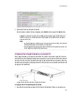


Detailed Directions
387
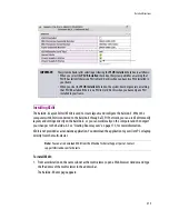
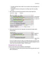
– The module status indicator shows whether the card (or module) is running normally (green) or in
safe mode (red).
– The signal status indicators reveals the presence of a valid input signal at the corresponding
connector.
3. Move the pointer to an input signal status indicator to view the associated signal format:
4. Click the arrow button at the end of each heading row to view detailed information about the
associated module:
In the case of a Kaleido-X multi-viewer model, you can identify which output card currently assumes
the
software master
role (and is thus assigned the multi-viewer’s IP address) by looking for the word
“master” next to the card’s identifier, for example: “OUTPUT A (master)”.
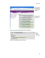
Viewing Kaleido-X Version Information
To view your multi-viewer’s system and software version information:
1. From a workstation on the same subnet, open a Web browser window and type the multi-viewer’s IP
address in the address bar.
1
Card type
Serial number
Version information
Input signal status
Input signal format
Status indicator
Expand details
Refresh
Reset card
Master card status
indicator
Summary of Contents for Kaleido-X
Page 1: ...Kaleido X User s Manual Part Number M770 2800 111 1 June 2011 ...
Page 8: ...viii toc ...
Page 33: ...Loading a Layout 25 Kaleido X16 ...
Page 34: ...26 Getting Started 2 Kaleido X 4RU ...
Page 152: ...144 Creating Logical Sources 7 ...
Page 178: ...170 Setting Up Rooms 8 ...
Page 244: ...236 Creating Layouts 9 ...
Page 253: ...Detailed Directions 245 3 Under Properties General type a Friendly name for the Action ...
Page 256: ...248 Creating Actions 10 ...
Page 272: ...264 Managing Kaleido RCP2 Users 11 ...
Page 348: ...340 Tally Interface Devices 13 ...
Page 350: ......
Page 352: ...344 Using the Serial to TCP IP Dispatcher 15 ...
Page 406: ...398 Index ...