


300
Routers & Kaleido-X
12
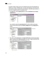
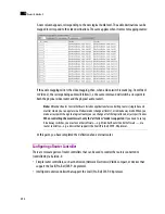
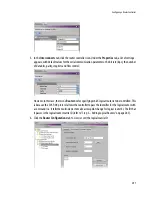
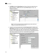
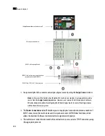
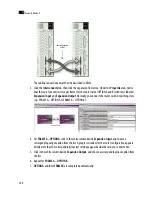
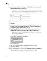
3. Click
OPTION A
(or
B
) under
Physical Routers
in the Routers list. Note that the physical levels are
automatically created—OPTION A (Video 120 × 48) and OPTION B (Video 120 × 48)—and
configured to the right size:
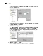
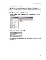
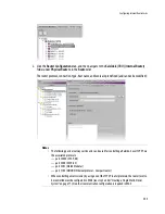
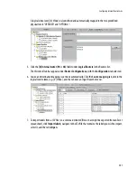
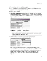
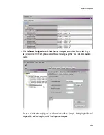
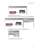
4. A Logical router is also automatically defined. Click the
[0] Internal router (96 × 48)
folder under
Logical Routers
in the Routers list. The number of sources and destinations are also predefined, and
cannot be modified manually. These numbers are determined by how many input (KXI) cards and
internal router cards are defined in the system: 16 sources per input card; 24 destinations per internal
router card, for a maximum of 96 × 48 (or 192 × 96 on a Kaleido-X expansion system):
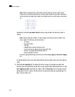
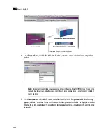
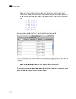
Note:
“120 × 48” refers to the physical router size including internal connections used for router
expansion. The actual size of each router card is 96 × 24.
Summary of Contents for Kaleido-X
Page 1: ...Kaleido X User s Manual Part Number M770 2800 111 1 June 2011 ...
Page 8: ...viii toc ...
Page 33: ...Loading a Layout 25 Kaleido X16 ...
Page 34: ...26 Getting Started 2 Kaleido X 4RU ...
Page 152: ...144 Creating Logical Sources 7 ...
Page 178: ...170 Setting Up Rooms 8 ...
Page 244: ...236 Creating Layouts 9 ...
Page 253: ...Detailed Directions 245 3 Under Properties General type a Friendly name for the Action ...
Page 256: ...248 Creating Actions 10 ...
Page 272: ...264 Managing Kaleido RCP2 Users 11 ...
Page 348: ...340 Tally Interface Devices 13 ...
Page 350: ......
Page 352: ...344 Using the Serial to TCP IP Dispatcher 15 ...
Page 406: ...398 Index ...