


Router Connections
303
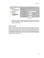
Router Connections
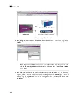
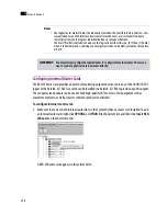
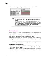
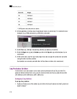
To be able to control an upstream router from the monitor wall, you must specify physical connections
between a number of multi-viewer inputs and external router outputs that feed them. When you want to
assign a source from the upstream router to a video monitor on the monitor wall, the Kaleido-X Software
uses this information to allocate a tie line (i.e. one of the multi-viewer’s physical input connectors that you
reserved for this purpose, and the upstream router’s output it is connected to), and initiate the appropriate
crosspoint change on the upstream router.
Note:
In the case of a Kaleido-X (7RU), signals entering the input cards are made available to the internal
router cards via the midplane (i.e. there is no cabling between the BNC outputs on the router cards and
the BNC inputs on the KXI cards).
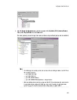
Logical router matrix ID
Summary of Contents for Kaleido-X
Page 1: ...Kaleido X User s Manual Part Number M770 2800 111 1 June 2011 ...
Page 8: ...viii toc ...
Page 33: ...Loading a Layout 25 Kaleido X16 ...
Page 34: ...26 Getting Started 2 Kaleido X 4RU ...
Page 152: ...144 Creating Logical Sources 7 ...
Page 178: ...170 Setting Up Rooms 8 ...
Page 244: ...236 Creating Layouts 9 ...
Page 253: ...Detailed Directions 245 3 Under Properties General type a Friendly name for the Action ...
Page 256: ...248 Creating Actions 10 ...
Page 272: ...264 Managing Kaleido RCP2 Users 11 ...
Page 348: ...340 Tally Interface Devices 13 ...
Page 350: ......
Page 352: ...344 Using the Serial to TCP IP Dispatcher 15 ...
Page 406: ...398 Index ...