


16
Getting Started
2
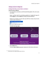
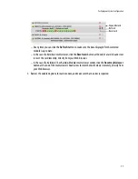
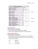
3. Move the pointer to an input signal status indicator to view the associated signal format.
4. Click the arrow button at the end of a module’s heading row to view more detailed information about
this module.
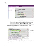
For example, in the case of a Kaleido-X multi-viewer, the heading rows show the card type, serial number,
firmware and safemode versions, a card status indicator, and input signal status indicators. The card
status indicator shows whether the card is running normally (green) or in safe mode (red). The signal
status indicators reveals the presence of a valid input signal at the corresponding connector.
Card type
Serial number
Version information
Input signal status
Input signal format
Status indicator
Summary of Contents for Kaleido-X
Page 1: ...Kaleido X User s Manual Part Number M770 2800 111 1 June 2011 ...
Page 8: ...viii toc ...
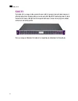
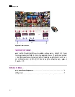
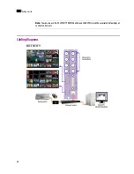
Page 33: ...Loading a Layout 25 Kaleido X16 ...
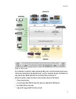
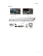
Page 34: ...26 Getting Started 2 Kaleido X 4RU ...
Page 152: ...144 Creating Logical Sources 7 ...
Page 178: ...170 Setting Up Rooms 8 ...
Page 244: ...236 Creating Layouts 9 ...
Page 253: ...Detailed Directions 245 3 Under Properties General type a Friendly name for the Action ...
Page 256: ...248 Creating Actions 10 ...
Page 272: ...264 Managing Kaleido RCP2 Users 11 ...
Page 348: ...340 Tally Interface Devices 13 ...
Page 350: ......
Page 352: ...344 Using the Serial to TCP IP Dispatcher 15 ...
Page 406: ...398 Index ...