


Troubleshooting
6 - 7
Standard Turntable Power Washer v. 4.0
The MART Corporation
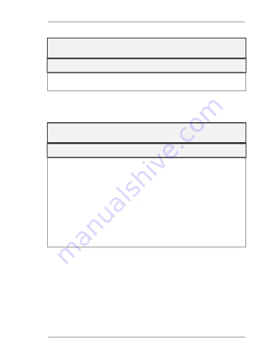
Problem:
Seal leakage at wash pump mounting plate
Check This:
Probable Cause(s)
Pump
Mechanical defects:
Throttle bushing failure
Shaft
Shaft-slinger failure
Fig. 6 - 7: Troubleshooting: Seal Leakage at Wash Pump Mounting Plate
Problem:
Wash pump or motor vibrates or is noisy
Check This:
Probable Cause(s)
Pump or motor
Bearings:
Need lubrication
Need to be replaced
Damaged
Pump
Throttle bushing failure
Pump & motor
Coupling:
Loose/dropped
Wearing out
Pump
Impeller:
Loose
Damaged
Pump
Clogged -- restricts impeller
Pipes
Pipe strains - discharge piping improperly connected
Thrust bearing
Snap ring has worn a groove in the bearing frame & is
spinning
Temperature too high
Pump cavitation
Fig. 6 - 8: Troubleshooting: Wash Pump or Motor Vibrates or Is Noisy
Summary of Contents for Cyclone 30 Series
Page 295: ...MART REVISION 06 06 06 Revision 03 OWNER S MANUAL for MART VERTICAL POWER WASHER PUMP...
Page 308: ...12 Fig 1 Main Pump Cut Away 1530 Frame Hardened Steel Throttle Bushing...
Page 310: ...14 Fig 2 Main Pump Cut Away 1530 Frame Composite Throttle Bushing...
Page 312: ...16 Fig 3 Main Pump Cut Away 12V Frame Composite Throttle Bushing...
Page 314: ...18 Fig 4 Boost Pump Cut Away 1530 Frame Composite Throttle Bushing...
Page 316: ...20 Fig 4 Boost Pump Cut Away 12V Frame Composite Throttle Bushing...