


79
Learning Basic Features
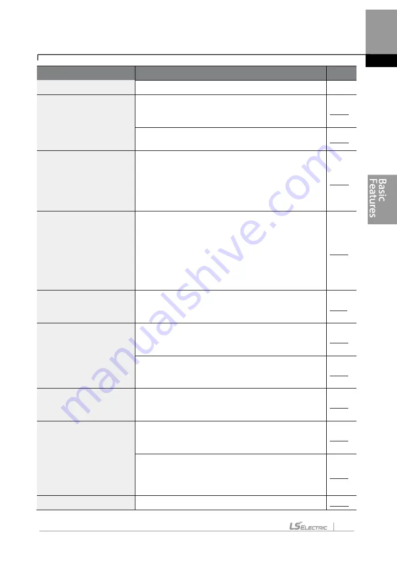
Basic Tasks
Description
Ref.
block inputs
Command source
configuration for RS-485
communication
Configures the inverter to accept communication
signals from upper level controllers, such as PLCs or
PCs.
Motor rotation control
Configures the inverter to limit a motor’s rotation
direction.
Automatic start-up at
power-on
Configures the inverter to start operating at power-on.
With this configuration, the inverter begins to run and
the motor accelerates as soon as power is supplied to
the inverter. To use automatic start-up configuration,
the operation command terminals at the terminal block
must be turned on.
Automatic restart after
reset of a fault trip
condition
Configures the inverter to start operating when the
inverter is reset following a fault trip. In this
configuration, the inverter starts to run and the motor
accelerates as soon as the inverter is reset following a
fault trip condition.
For automatic start-up configuration to work, the
operation command terminals at the terminal block
must be turned on.
Acc/Dec time configuration
based on the Max.
Frequency
Configures the acceleration and deceleration times for
a motor based on a defined maximum frequency.
Acc/Dec time configuration
based on the frequency
reference
Configures acceleration and deceleration times for a
motor based on a defined frequency reference.
Multi-stage Acc/Dec time
configuration using the
multi-function terminal
Configures multi-stage acceleration and deceleration
times for a motor based on defined parameters for the
multi-function terminals.
Acc/Dec time transition
speed (frequency)
configuration
Enables modification of acceleration and deceleration
gradients without configuring the multi-functional
terminals.
Acc/Dec pattern
configuration
Enables modification of the acceleration and
deceleration gradient patterns. Basic patterns to
choose from include linear and S-curve patterns.
Acc/Dec stop command
Stops the current acceleration or deceleration and
controls motor operation at a constant speed. Multi-
function terminals must be configured for this
command.
Linear V/F pattern
Configures the inverter to run a motor at a constant
Summary of Contents for LSLV-H100 Series
Page 17: ...Preparing the Installation 4 37 90 kW 3 Phase ...
Page 18: ...Preparing the Installation 5 110 132 kW 3 Phase ...
Page 19: ...Preparing the Installation 6 160 185 kW 3 Phase ...
Page 20: ...Preparing the Installation 7 220 250 kW 3 Phase ...
Page 21: ...Preparing the Installation 8 315 400 kW 3 Phase ...
Page 22: ...Preparing the Installation 9 500 kW 3 Phase ...
Page 35: ...Installing the Inverter 22 ...
Page 50: ...37 Installing the Inverter Input and Output Control Terminal Block Wiring Diagram ...
Page 104: ...91 Learning Basic Features 0 10 V Input Voltage Setting Details V1 Quantizing ...
Page 181: ...168 Learning Advanced Features PID Command Block ...
Page 182: ...169 Learning Advanced Features ...
Page 183: ...170 Learning Advanced Features PID Feedback Block ...
Page 184: ...171 Learning Advanced Features PID Output Block ...
Page 185: ...172 Learning Advanced Features PID Output Mode Block ...
Page 198: ...185 Learning Advanced Features EPID1 Control block ...
Page 199: ...186 Learning Advanced Features EPID2 Control block ...
Page 220: ...207 Learning Advanced Features ...
Page 235: ...222 Learning Advanced Features The Time Chart for the Exception Day ...
Page 506: ...Table of Functions 493 ...
Page 520: ...Table of Functions 507 8 16 4 Cooling Tower MC4 Group ...
Page 549: ...Troubleshooting 536 ...
Page 569: ...Technical Specification 556 11 3 External Dimensions 0 75 30 kW 3 phase 37 90 kW 3 phase ...
Page 570: ...Technical Specification 557 110 185 kW 3 phase ...
Page 601: ...588 ...
Page 602: ...589 ...
Page 603: ...590 ...


