


166
Learning Advanced Features
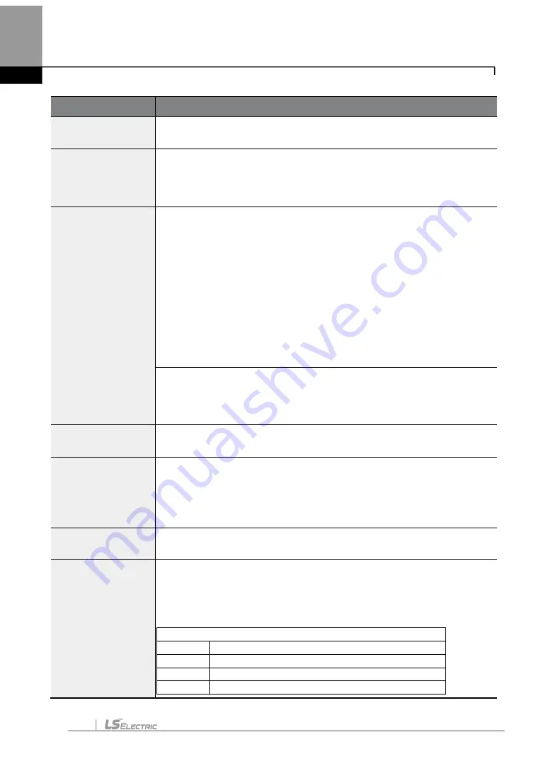
Code
Description
feedback value is between the maximum and minimum value, this code
maintains the PID output.
PID-25
PID P-Gain1
PID-32
PID P-Gain2
Set the output ratio for differences (errors) between the reference and
feedback. If the P Gain is set to 50%, then 50% of the error is output.
PID-26
PID I- Time 1
PID-33
PID I- Time 2
Sets the time to output accumulated errors. When the error is 100%,
the time taken for 100% output is set. When the integral time (PID I-
Time) is set to 1 second, 100% output occurs after 1 second of the error
remaining at 100%. Differences in a normal state can be reduced by
PID I Time. When the multi-
function terminal block is set to ‘24 (I-Term
Clear)’ and is turned on, all of the accumulated errors are deleted.
PID output (final frequency reference) is affected by the gains set at
PID-26, PID-33, and the Acc/Dec times to achieve the PID output
change based on the DRV-03 and DRV-04 settings. Therefore,
consider the relationship between these values when configuring the
gains and the Acc/Dec times.
PID-27
PID D-Time 1
PID-34
PID D-Time 2
Sets the output volume for the rate of change in errors. If the differential
time (PID D-Time) is set to 1 ms and the rate of change in errors per
sec is 100%, output occurs at 1% per 10 ms.
PID-28 PID FF-
Gain
Sets the ratio that adds the target to the PID output. Adjusting this value
leads to a faster response.
PID-29
PID Out LPF
Used when the PID controller output changes too quickly or the entire
system is unstable, due to severe oscillation. In general, a lower value
(default value=0) is used to speed up response time, but in some cases
a higher value increases stability. The higher the value, the more stable
the PID controller output is, but the slower the response time.
PID-30 PID Limit Hi,
PID-31 PID Limit Lo
Limit the output of the controller.
PID-35
PID Out Mode
Selects one of the PID output modes to modify the PID output.
Modifications can be made by adding input values and the main
operation frequency of the PID output to the final PID output value.
The following table lists the 5 modes that are available.
Setting
0
PID Output
1
PID+Main Freq
2
PID+EPID1 Out
3
PID+EPID1+Main
Summary of Contents for LSLV-H100 Series
Page 17: ...Preparing the Installation 4 37 90 kW 3 Phase ...
Page 18: ...Preparing the Installation 5 110 132 kW 3 Phase ...
Page 19: ...Preparing the Installation 6 160 185 kW 3 Phase ...
Page 20: ...Preparing the Installation 7 220 250 kW 3 Phase ...
Page 21: ...Preparing the Installation 8 315 400 kW 3 Phase ...
Page 22: ...Preparing the Installation 9 500 kW 3 Phase ...
Page 35: ...Installing the Inverter 22 ...
Page 50: ...37 Installing the Inverter Input and Output Control Terminal Block Wiring Diagram ...
Page 104: ...91 Learning Basic Features 0 10 V Input Voltage Setting Details V1 Quantizing ...
Page 181: ...168 Learning Advanced Features PID Command Block ...
Page 182: ...169 Learning Advanced Features ...
Page 183: ...170 Learning Advanced Features PID Feedback Block ...
Page 184: ...171 Learning Advanced Features PID Output Block ...
Page 185: ...172 Learning Advanced Features PID Output Mode Block ...
Page 198: ...185 Learning Advanced Features EPID1 Control block ...
Page 199: ...186 Learning Advanced Features EPID2 Control block ...
Page 220: ...207 Learning Advanced Features ...
Page 235: ...222 Learning Advanced Features The Time Chart for the Exception Day ...
Page 506: ...Table of Functions 493 ...
Page 520: ...Table of Functions 507 8 16 4 Cooling Tower MC4 Group ...
Page 549: ...Troubleshooting 536 ...
Page 569: ...Technical Specification 556 11 3 External Dimensions 0 75 30 kW 3 phase 37 90 kW 3 phase ...
Page 570: ...Technical Specification 557 110 185 kW 3 phase ...
Page 601: ...588 ...
Page 602: ...589 ...
Page 603: ...590 ...


