


226
Learning Advanced Features
The parameters in the table above shows the frequency command sources for the keypad
and the operation command sources for the Time Event.
The following is an example of an inverter operation utilizing the Time Period modules 1 and
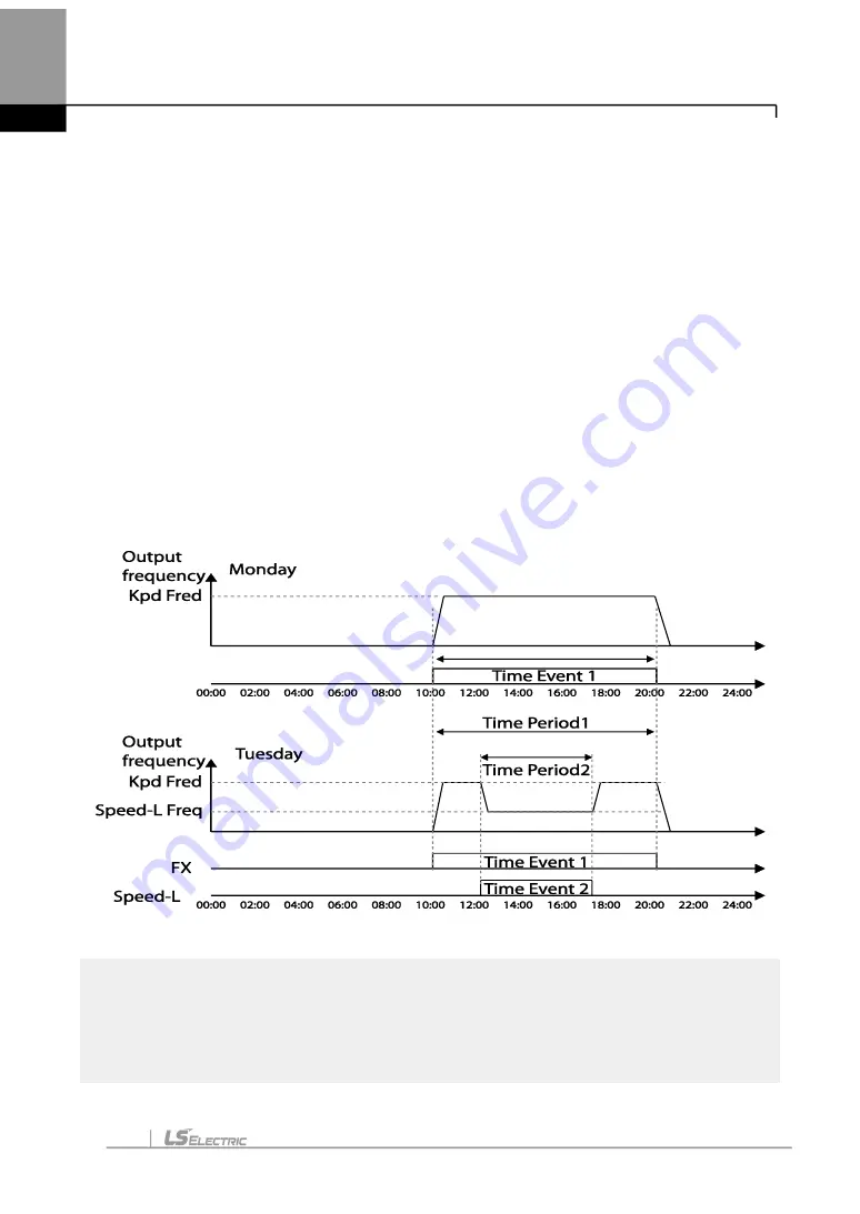
2 with Time Events 1 and 2:
Time Period 1 is used to operate the inverter on Mondays and Tuesdays from 10AM to
8PM. Time Period 2 is used to operate the inverter on Tuesday from 12PM to 5PM.
Time Event 1 triggers forward operations based on the frequency input on the keypad and
continues the operation for the time set at Time Period module 1. Time Event 2 operates
the inverter at Speed-L for the time set at Time Period module 2.
On Mondays, the inverter operates in the forward direction based on the frequency input on
the keypad from 10AM to 8PM (Time Event 1). On Tuesdays, it operates again in the
forward direction based on the keypad frequency input from 10AM to 12PM (Time Event 1),
and then operates at Speed-L from 12PM to 5PM (Time Event 2). When the operation
assigned by Time Event 2 is complete, the inverter resumes its Time Event 1 operation (the
inverter operates based on the keypad frequency input from 5PM to 8PM).
<An example of Time Event>
Note
When repetitive frequency commands related to the frequency input command occur while the
Time Event function is performing, Time Event performs its function in the order of the
frequency command sources set in Freq Ref Src for DRV-07 (followed by Jog operation and
multi-step acc/dec).
Summary of Contents for LSLV-H100 Series
Page 17: ...Preparing the Installation 4 37 90 kW 3 Phase ...
Page 18: ...Preparing the Installation 5 110 132 kW 3 Phase ...
Page 19: ...Preparing the Installation 6 160 185 kW 3 Phase ...
Page 20: ...Preparing the Installation 7 220 250 kW 3 Phase ...
Page 21: ...Preparing the Installation 8 315 400 kW 3 Phase ...
Page 22: ...Preparing the Installation 9 500 kW 3 Phase ...
Page 35: ...Installing the Inverter 22 ...
Page 50: ...37 Installing the Inverter Input and Output Control Terminal Block Wiring Diagram ...
Page 104: ...91 Learning Basic Features 0 10 V Input Voltage Setting Details V1 Quantizing ...
Page 181: ...168 Learning Advanced Features PID Command Block ...
Page 182: ...169 Learning Advanced Features ...
Page 183: ...170 Learning Advanced Features PID Feedback Block ...
Page 184: ...171 Learning Advanced Features PID Output Block ...
Page 185: ...172 Learning Advanced Features PID Output Mode Block ...
Page 198: ...185 Learning Advanced Features EPID1 Control block ...
Page 199: ...186 Learning Advanced Features EPID2 Control block ...
Page 220: ...207 Learning Advanced Features ...
Page 235: ...222 Learning Advanced Features The Time Chart for the Exception Day ...
Page 506: ...Table of Functions 493 ...
Page 520: ...Table of Functions 507 8 16 4 Cooling Tower MC4 Group ...
Page 549: ...Troubleshooting 536 ...
Page 569: ...Technical Specification 556 11 3 External Dimensions 0 75 30 kW 3 phase 37 90 kW 3 phase ...
Page 570: ...Technical Specification 557 110 185 kW 3 phase ...
Page 601: ...588 ...
Page 602: ...589 ...
Page 603: ...590 ...


