205
Learning Advanced Features
Code
Description
PRT-96 LDT Rst
Cnt
PRT-97 LDT Rst
Cnt M
PRT-98 LDT Cnt
Clr T
When the LDT trip occurs, the number of automatic restart is set by PRT-
96.
If an LDT trip occurs, the inverter automatically restarts after the time set
in PRT-77 (LDT Restart DT) has elapsed. The PRT-97 is incremented by
1 each time it is automatically restarted.
When the value of PRT-97 becomes equal to PRT-96, it does not try to
restart automatically.
The LDT trip will be restarted within the time set in PRT-98 after auto
restart
If not, PRT-97 is initialized to 0.
OUT-31
–35
Relay 1
–5
Sets one of the output relays to ‘32 (LDT)’ to monitor the level detection
status.
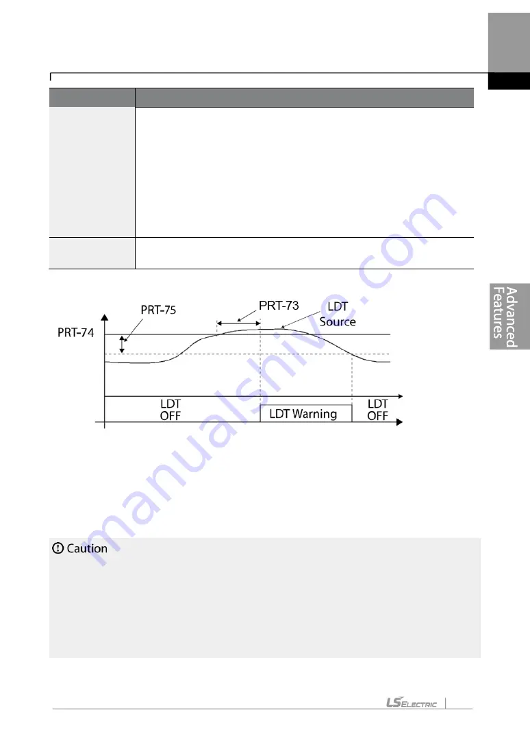
<An example of PRT-71 set to (1: Above Level )>
As shown in the figure above, level detection can be carried out (relay output is
‘on’) as the
output frequency is above PRT-76 and the detection value is greater than the value of PRT-
74.
The LDT operation is released if the value is less than the value subtracted from the value of
band of, when the value of the feedback is set from PRT-74 to PRT-75.
•
The LDT operation is carried out if the inverter operation is above PRT-74.
•
Modify PRT-74 and PRT-75 appropriately when modifying LDT Source of PRT-71.
•
PRT-74 and PRT-75 become default value if the LDT Source is modified.
•
PRT-77 (Restart DT) and PRT-08 (RST restart) features operate separately.
•
The inverter waits until the delay time set at PRT-73 (LDT Dly Time) before it operates
based on the setting in LDT-70 when the level detection time condition is met.
Summary of Contents for LSLV-H100 Series
Page 17: ...Preparing the Installation 4 37 90 kW 3 Phase ...
Page 18: ...Preparing the Installation 5 110 132 kW 3 Phase ...
Page 19: ...Preparing the Installation 6 160 185 kW 3 Phase ...
Page 20: ...Preparing the Installation 7 220 250 kW 3 Phase ...
Page 21: ...Preparing the Installation 8 315 400 kW 3 Phase ...
Page 22: ...Preparing the Installation 9 500 kW 3 Phase ...
Page 35: ...Installing the Inverter 22 ...
Page 50: ...37 Installing the Inverter Input and Output Control Terminal Block Wiring Diagram ...
Page 104: ...91 Learning Basic Features 0 10 V Input Voltage Setting Details V1 Quantizing ...
Page 181: ...168 Learning Advanced Features PID Command Block ...
Page 182: ...169 Learning Advanced Features ...
Page 183: ...170 Learning Advanced Features PID Feedback Block ...
Page 184: ...171 Learning Advanced Features PID Output Block ...
Page 185: ...172 Learning Advanced Features PID Output Mode Block ...
Page 198: ...185 Learning Advanced Features EPID1 Control block ...
Page 199: ...186 Learning Advanced Features EPID2 Control block ...
Page 220: ...207 Learning Advanced Features ...
Page 235: ...222 Learning Advanced Features The Time Chart for the Exception Day ...
Page 506: ...Table of Functions 493 ...
Page 520: ...Table of Functions 507 8 16 4 Cooling Tower MC4 Group ...
Page 549: ...Troubleshooting 536 ...
Page 569: ...Technical Specification 556 11 3 External Dimensions 0 75 30 kW 3 phase 37 90 kW 3 phase ...
Page 570: ...Technical Specification 557 110 185 kW 3 phase ...
Page 601: ...588 ...
Page 602: ...589 ...
Page 603: ...590 ...